POWER DISTRIBUTION
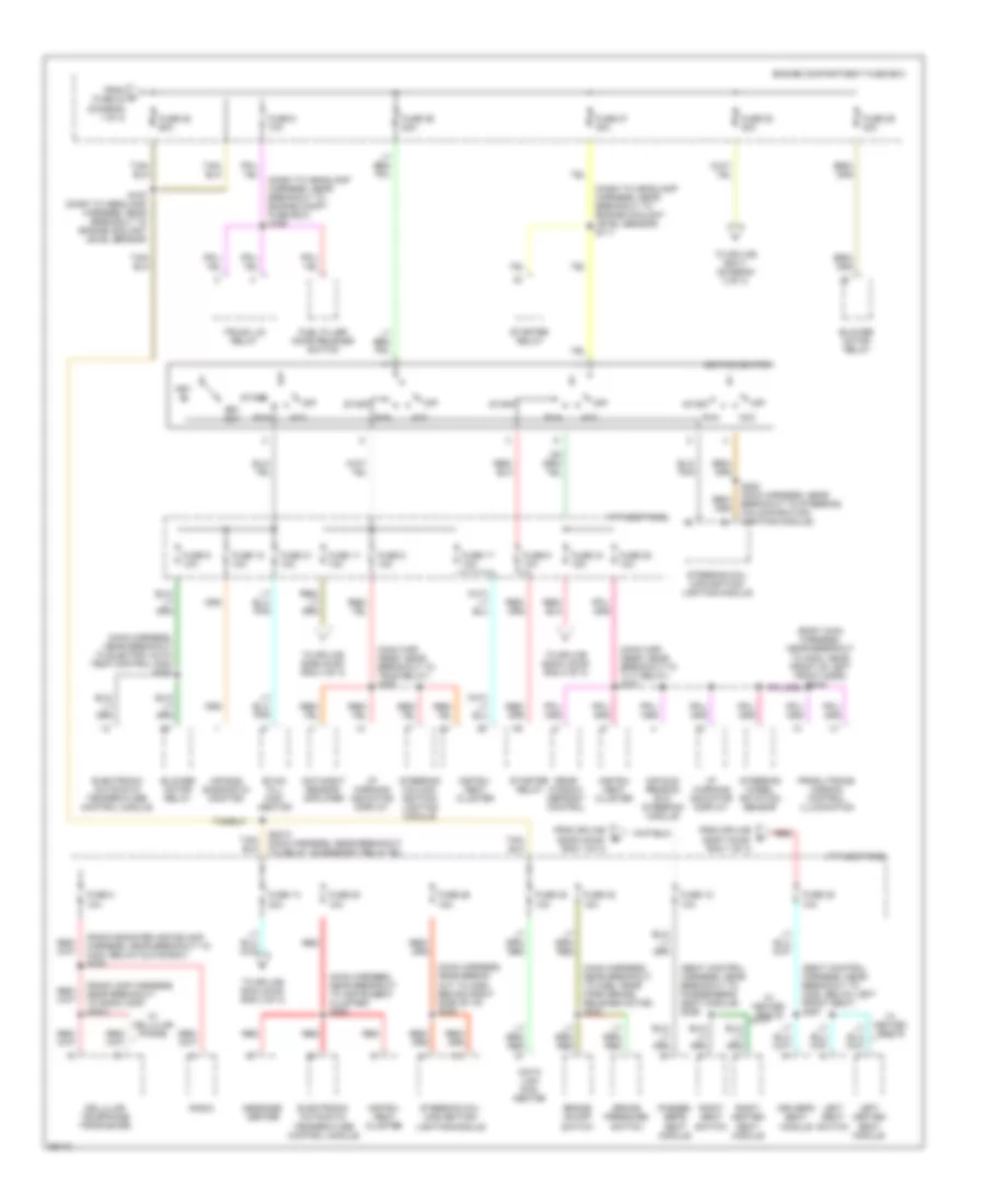
Power Distribution Wiring Diagram (1 of 3) for Lincoln Mark VIII LSC 1997
 https://portal-diagnostov.com/license.html
Automotive Electricians Portal FZCO
Automotive Electricians Portal FZCO
https://portal-diagnostov.com/license.html
https://portal-diagnostov.com/license.html
Automotive Electricians Portal FZCO
Automotive Electricians Portal FZCO
List of elements for Power Distribution Wiring Diagram (1 of 3) for Lincoln Mark VIII LSC 1997:
- (dash to head- lamp harness, near breakout to evac/fill connector) s164
- (dash to head- lamp harness, near breakout to variable load control module) s161
- (dash to headlamp harness, near breakout to c140, electric air management relay) s154
- (dash to headlamp harness, near breakout to c189, near left front brake sensor) s121
- (main harness, near breakout to c201, near left side of safety wall) s2007
- (main harness, near breakout to connector bracket) s2002
- (main harness, near breakout to tilt relay) s294
- (radio amplifier harness, near breakout to radio amplifier) s411
- Air bag diagnostic monitor
- Air suspen- sion comp- ressor relay
- Air suspension/ evo steering module
- Anti-lock brake con- trol module
- Battery
- Canada only
- Compact disc changer
- Daytime run- ing lamps module
- Driver's seat module
- Electric air management relay
- Electric air management solenoid
- Engine compartment fuse box
- Evac/fill connector
- From a fuse 10 (diagram 1 of 3)
- From b fuse 17 (diagram 1 of 3)
- Fuel pump relay
- Fuse 1 10a
- Fuse 10 20a
- Fuse 12 15a
- Fuse 13 60a
- Fuse 14 30a
- Fuse 15 30a
- Fuse 16 20a
- Fuse 17 30a
- Fuse 18 30a
- Fuse 19 30a
- Fuse 2 15a
- Fuse 20 30a
- Fuse 21 20a
- Fuse 22 60a
- Fuse 23 40a
- Fuse 24 40a
- Fuse 4 15a
- Fuse 6 10a
- Fuse 8 20a
- Generator/voltage regulator
- High beam relay
- Horn relay
- Left lumbar switch
- Passen- ger's seat module
- Pcm power relay
- Powertrain control module
- Radio amplifier
- Rear window defrost control
- Red
- Right lumbar switch
- S101 (engine ctrl har- ness, in break- out to engine compt fuse box)
- S103 (engine ctrl harness, near breakout to engine compt fuse box)
- S110 (dash to headlamp harness, near breakout to engine compt fuse box)
- S168 (dash to headlamp harness, near breakout to engine coolant level sensor)
- S212 (dash to headlamp harness, near breakout to air suspension/evo steering mod)
- S310 (seat control harness, near breakout to passenger's seat module)
- S358 (seat control harness, near breakout side driver's seat module)
- Starter motor/ solenoid
- Steering col- umn/ignition/ lighting module
- Tan/ red
- Tele relay
- Tilt relay
- Tilt/tele common relay
- To fuse 12 (diagram 1 of 3)
- To fuse 12, i/p fuse panel (diagram 2 of 3)
- To fuse 18 (diagram 1 of 3)
- To fuse 25 (diagram 2 of 3)
- To fuse 35, i/p fuse panel (diagram 2 of 3)
- To splice s2009 (diagram 3 of 3)
- To splice s290 (diagram 3 of 3)
- Variable load control module
- W/ cd changer
- W/ jbl
- W/o jbl
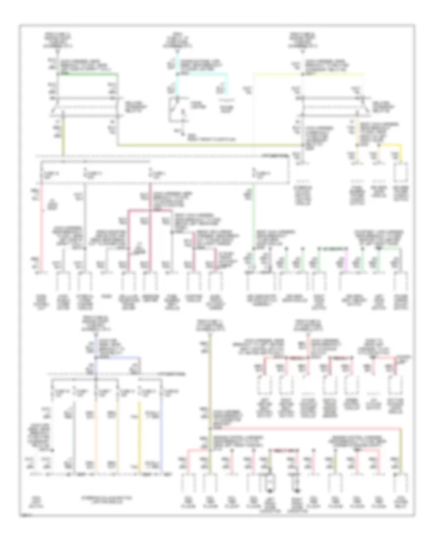
Power Distribution Wiring Diagram (2 of 3) for Lincoln Mark VIII LSC 1997
 https://portal-diagnostov.com/license.html
Automotive Electricians Portal FZCO
Automotive Electricians Portal FZCO
https://portal-diagnostov.com/license.html
https://portal-diagnostov.com/license.html
Automotive Electricians Portal FZCO
Automotive Electricians Portal FZCOList of elements for Power Distribution Wiring Diagram (2 of 3) for Lincoln Mark VIII LSC 1997:
- (body main harness, near breakout to g300, near front of left front door)
- (dash to headlamp harness, near breakout to engine compt fuse box) s166
- (dash to headlamp harness, near breakout to engine coolant level sensor) s111
- (main har- ness, near breakout to tele relay) s293
- (main har- ness, near breakout to tilt relay) s227
- (main harness, near break- out to c290, behind right side of i/p) s285
- (main harness, near breakout to c298, near park brake release motor) s232
- (main harness, near breakout to electric auto temp control mod) s288
- (main harness, near breakout to instrument cluster) s292
- (radio amp harness, near breakout to radio amp) s2021
- (radio booster and eq amp harness, near breakout to c223, below glove box) s226
- (seat control harness, near breakout to c352, below left front seat) s357
- (seat control harness, near breakout to passenger's seat module) s359
- Acc
- Air bag diagnostic monitor
- Air sus- pension evo steering module
- Blower motor relay
- Brake on/off switch
- Brake pressure switch
- Cellular telephone tranciever
- Data link con- nector
- Day/night sensor/ amplifier
- Driver's seat module
- Electronic automatic temperature control module
- Engine compartment fuse box
- Evac/ fill con- nector
- From c fuse 24 (diagram 1 of 3)
- From splice s2002 (diag- ram 1 of 3)
- From splice s2007 (diag- ram 1 of 3)
- Fuel filler door release switch
- Fuse 11 10a
- Fuse 12 10a
- Fuse 14 30a
- Fuse 15 10a
- Fuse 17 10a
- Fuse 2 10a
- Fuse 20 10a
- Fuse 21 10a
- Fuse 25 60a
- Fuse 26 15a
- Fuse 26 20a
- Fuse 27 30a
- Fuse 28 10a
- Fuse 28 30a
- Fuse 29 40a
- Fuse 32 15a
- Fuse 34 15a
- Fuse 35 10a
- Fuse 38 10a
- Fuse 5 10a
- Fuse 6 10a
- Fuse 9 10a
- I/p fuse panel
- I/p warning indicator display
- Ignition switch
- Instru- ment cluster
- Key in
- Key out
- Left heated seat module
- Left seat switch
- Message center
- Off
- Passen- ger's seat module
- Prndl/trans- mission control illumination
- Radio
- Rear window defrost control
- Red
- Right heated seat module
- Right seat switch
- Run
- S167 (dash to headlamp harness, near breakout to engine coolant level sensor)
- S2010 (main harness, near breakout to delay accessory relay #2)
- S282 (main harness, near breakout to steering column/ignition/ lighting module)
- Start
- Starter relay
- Steering col- umn/ignition/ lighting module
- Steering column/ ignition/ lighting module
- Steering wheel rotation sensor
- To splice s2003 (diag- ram 3 of 3)
- To splice s2011 (diagram 3 of 3)
- To splice s299 (diag- ram 3 of 3)
- To splice s323 (diag- ram 3 of 3)
- Trunk lid relay
- W/ cellular phone
- W/ heated seats
Power Distribution Wiring Diagram (3 of 3) for Lincoln Mark VIII LSC 1997
 https://portal-diagnostov.com/license.html
Automotive Electricians Portal FZCO
Automotive Electricians Portal FZCO
https://portal-diagnostov.com/license.html
https://portal-diagnostov.com/license.html
Automotive Electricians Portal FZCO
Automotive Electricians Portal FZCOList of elements for Power Distribution Wiring Diagram (3 of 3) for Lincoln Mark VIII LSC 1997:
- (body main harness, near breakout to c308, behind left rear side panel) s363
- (body main harness, near breakout to driver's door module) s506
- (body main harness, near breakout to g300, near front of left front door) s322
- (console panel har- ness, near breakout to cigar lighter) s323
- (courtesy lamp harness, near breakout to c506, near bottom center of left front door) s510
- (dash to headlamp harness, to a/c cycling switch) s171
- (engine control harness, near breakout to c166, rear corner of engine compt) s114
- (engine control harness, near breakout to c175, near left front ho2s #21) s119
- (main har- ness, near breakout to delayed accessory relay #2) s2012
- (main har- ness, near breakout to tele relay) s2009
- (main harness, in breakout to delayed accessory relay #1) s289
- (main harness, near breakout to c201, near left side of safety wall) s2014
- (main harness, near breakout to c201, near left side of safety wall) s290
- (main harness, near breakout to c276, to air bag diag- nostic monitor) s287
- (main harness, near breakout to connector bracket) s299
- (main harness, near breakout to delayed accessory relay #2) s2011
- (main harness, near breakout to i/p dimming switch) s2003
- (main harness, near breakout to left heated seat control switch) (w/ heated seats only) s2015
- (radio booster and eq amp har- ness, near break- out to connector) s233
- (rear view mirror harness, near break- out to electronic day/night mirror) s906
- A/c cycling switch
- C287
- C289
- Canada only
- Cellular telephone trans- ceiver
- Cigar lighter
- Coil per plug #1
- Coil per plug #2
- Coil per plug #3
- Coil per plug #4
- Coil per plug #5
- Coil per plug #6
- Coil per plug #7
- Coil per plug #8
- Compass module
- Daytime running lamps module
- Delayed accessory relay #1
- Delayed accessory relay #2
- Digital trans- mission range sensor
- Driver's door module
- Driver's power window switch
- Driver's seat memory switch
- Elec- tronic day/night mirror
- From fuse 11, i/p fuse panel (diagram 2 of 3)
- From fuse 14, engine compt fuse box (diagram 1 of 3)
- From fuse 14, i/p fuse panel (diagram 2 of 3)
- From fuse 22, engine compt fuse box (diagram 1 of 3)
- From fuse 28, engine compt fuse box (diagram 2 of 3)
- From fuse 34, i/p fuse panel (diagram 2 of 3)
- Fuse 1 10a
- Fuse 10 30a
- Fuse 13 15a
- Fuse 16 20a
- Fuse 19 10a
- Fuse 25 10a
- Fuse 31 10a
- Fuse 4 10a
- Fuse 41 10a
- Fuse 7 15a
- G203 (right front floor plan)
- I/p fuse panel
- Intake manifold runner control module
- Interval wiper/ washer module
- Keyless entry keypad switch assembly
- Left door lock switch
- Left heated seat control switch
- Left radio noise capacitor
- Main light switch
- Message center
- Moon- roof control unit
- Nca
- Pass- enger's power window switch
- Pass- enger's seat module
- Pcm power relay
- Power mirror adjust switch
- Power point
- Radio
- Right door lock switch
- Right heated seat control switch
- Right radio noise capacitor
- Speed control module
- Steering column/ ignition/ lighting module
- Steering column/ignition/ lighting module
- Tan
- W/ cell phone
- W/ elec- tronic day/night mirror
- W/ moon roof
- Wind- shield wiper motor

 Čeština
 Dansk
Dansk Deutsch
 Ελληνικά
 English
 English
 Español
 Suomi
Suomi Français
 Français
 עברית
עברית Hrvatski
 Magyar
 Italiano
 日本語
日本語 Nederlands
 Polski
 Português
 Português
 Română
 Русский
 Slovenčina
 Slovenščina
 Svenska
 Türkçe
 中文 (中国)
