ENGINE PERFORMANCE
4.0L
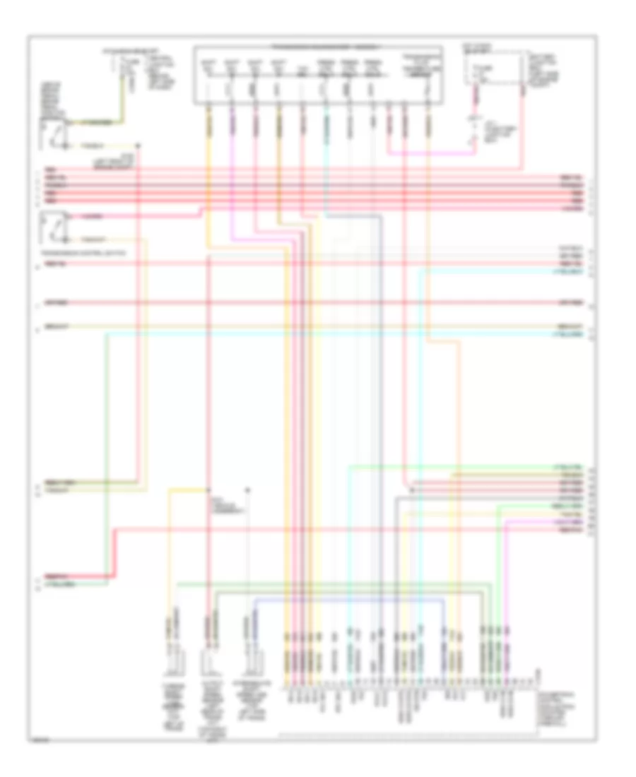
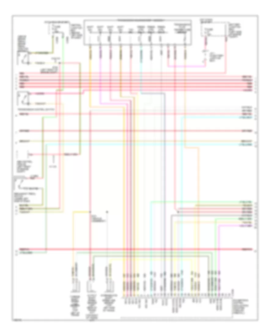
4.0L, Engine Performance Wiring Diagrams (1 of 4) for Ford Explorer 2002
 https://portal-diagnostov.com/license.html
Automotive Electricians Portal FZCO
Automotive Electricians Portal FZCO
https://portal-diagnostov.com/license.html
https://portal-diagnostov.com/license.html
Automotive Electricians Portal FZCO
Automotive Electricians Portal FZCO
List of elements for 4.0L, Engine Performance Wiring Diagrams (1 of 4) for Ford Explorer 2002:
- (behind left side of dash) s231
- (center of dash)
- (mounted on master cylinder) brake pressure switch
- (right rear of engine compt)
- (right rear of engine compt) g104
- 15a
- 4wd
- 4wd lo
- A/c rly
- A/c sw
- A/c system
- Ac demand
- Anti-theft system
- Audio unit
- Battery
- Battery junction box (left side of engine compt)
- Brake in
- C1117
- C175a
- C201a
- C240a
- Can vent
- Charging system
- Cruise control system
- Cruise set
- Data link connector (behind left side of dash)
- Early prod
- Evap pu
- Evaporative emission (evap) canister vent valve (right center of vehicle)
- F pmp pwr
- Fuse 15a
- Fuse 40a
- Fuse 5a
- G101 (behind left front headlamp)
- G103 (right front of engine compt)
- G104 (right rear of engine)
- G105 (right rear of engine compt)
- Generic electronic module (early production) (behind right side of dash)
- Ground
- Hot at all times
- Hot in run or start
- Iat in
- Ign
- Ind ctrl
- Ind input
- J/c 1
- J/c 2
- Late prod
- Maf out
- Mass airflow (maf) sensor (right front of engine compartment)
- Od off
- Passive anti-theft transceiver (on steering column)
- Pcm power diode
- Pcm power relay
- Pgm sig
- Powertrain control module (pcm) (mounted through firewall)
- Pres sw
- Red
- Red/pnk
- Return
- Rly ctrl
- Rx sig
- S116
- S127 (right front of engine compt)
- S129
- S130
- S131
- S132
- S135
- S210
- S211
- Scp bus +
- Scp bus -
- Sens rtn
- Spd ctrl
- Spd sw
- St mtr
- Starting system
- Tank press
- Transmission control system
- Tx sig
- V ref
- Vapor manage- ment valve (left rear of engine compt)
- Vss
- Windshield wiper motor (late production) (left side of engine compt)
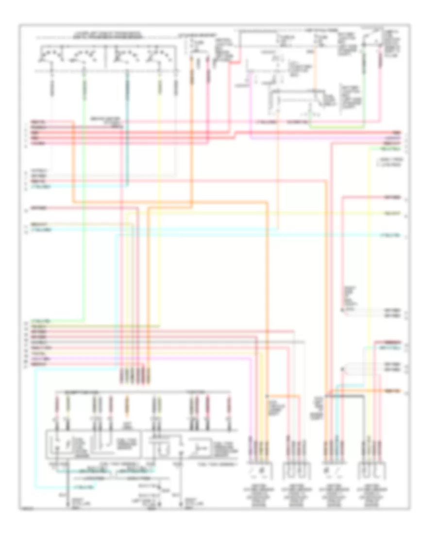
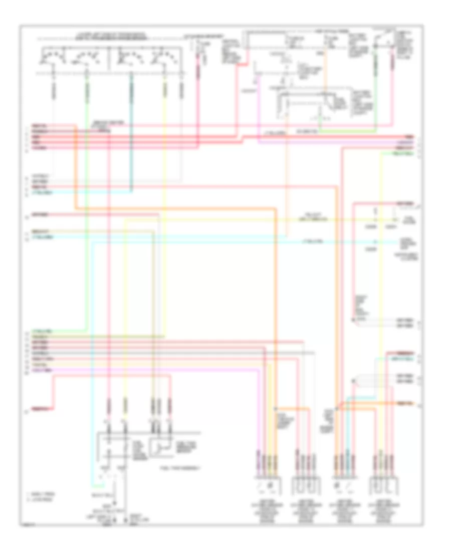
4.0L, Engine Performance Wiring Diagrams (2 of 4) for Ford Explorer 2002
 https://portal-diagnostov.com/license.html
Automotive Electricians Portal FZCO
Automotive Electricians Portal FZCO
https://portal-diagnostov.com/license.html
https://portal-diagnostov.com/license.html
Automotive Electricians Portal FZCO
Automotive Electricians Portal FZCOList of elements for 4.0L, Engine Performance Wiring Diagrams (2 of 4) for Ford Explorer 2002:
- (above brake pedal) brake pedal position switch
- Battery junction box (left side of engine compt)
- C175b
- C270d
- Central junction box (behind left side of dash)
- Epc sol
- Fuse 15a
- H2os 12 htr
- H2os 12 in
- H2os 22 htr
- H2os 22 in
- Hot in run or start
- Intermediate shaft speed (iss) sensor (top left side of trans)
- Iss
- J/c 1 (in battery junction box)
- Oss
- Output shaft speed sensor (left rear of trans) (a/t) (top right of trans) (m/t)
- Pcs b
- Pcs c
- Powertrain control module (pcm) (mounted through firewall)
- Press ctrl sol a
- Press ctrl sol b
- Press ctrl sol c
- Red
- Red/pnk
- S101 (vehicle underbody)
- S120 (left front of engine compt)
- Shift sol a
- Shift sol b
- Shift sol c
- Shift sol d
- Sig rtn
- Ss a
- Ss b
- Ss c
- Ss d
- Tcc sol
- Tft
- Tr1
- Tr2
- Tr3a
- Tr4
- Transmission control switch
- Transmission fluid temperature sensor
- Transmission solenoid body assembly
- Tss
- Turbine shaft speed (tss) sensor (a/t) (top left of trans)
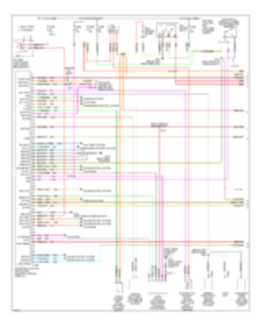
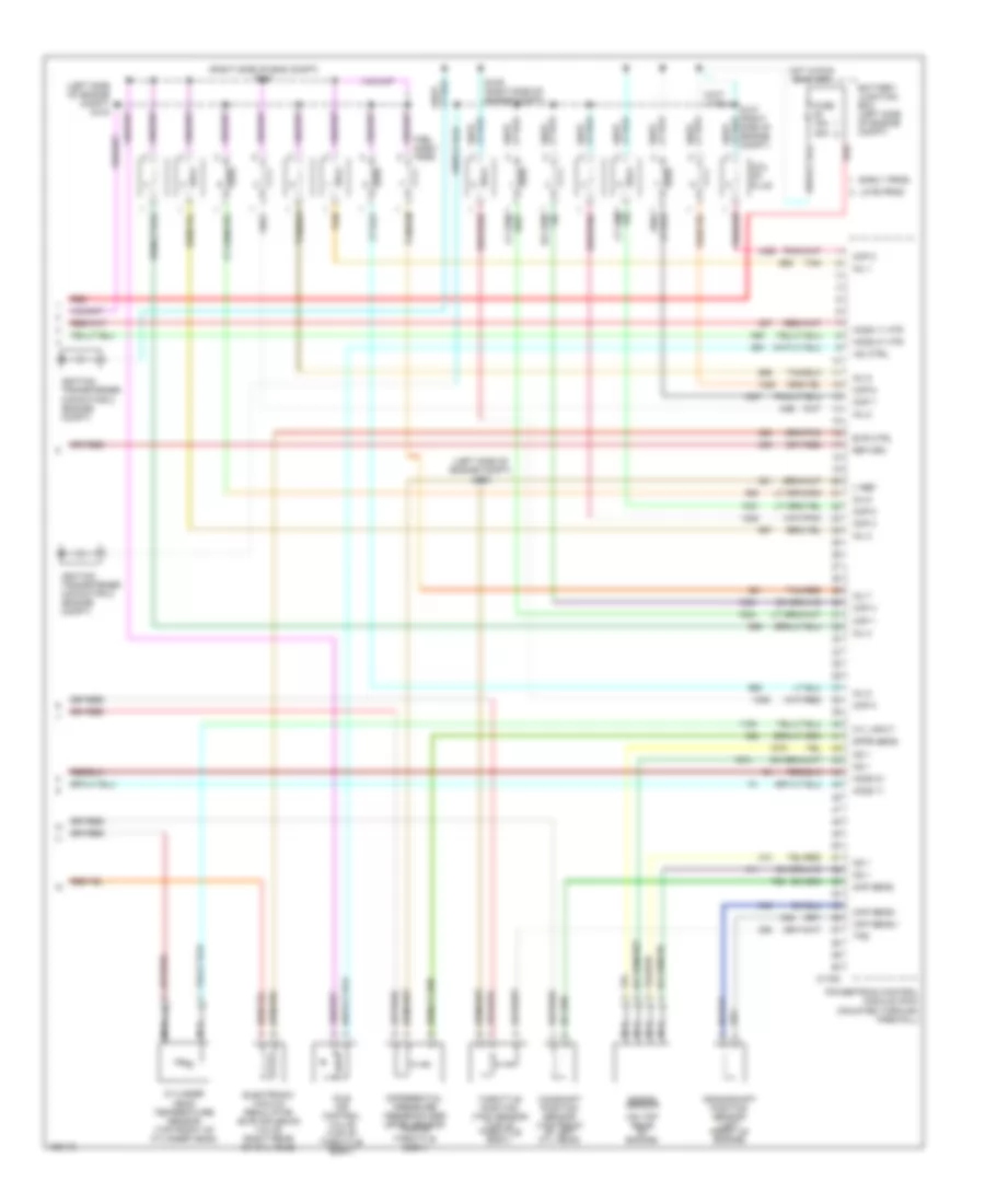
4.0L, Engine Performance Wiring Diagrams (3 of 4) for Ford Explorer 2002
 https://portal-diagnostov.com/license.html
Automotive Electricians Portal FZCO
Automotive Electricians Portal FZCO
https://portal-diagnostov.com/license.html
https://portal-diagnostov.com/license.html
Automotive Electricians Portal FZCO
Automotive Electricians Portal FZCOList of elements for 4.0L, Engine Performance Wiring Diagrams (3 of 4) for Ford Explorer 2002:
- (behind center of dash) s208
- (left side "a" pillar) g300
- (lower left side of transmission) digital transmission range sensor
- (not used)
- (right "d" pillar) g401
- (right side of eng compt)
- Battery junction box (left side of engine compt)
- C270a
- Central junction box (behind left side of dash) c270f
- Early prod
- Except flex fuel
- Flex fuel
- Fuel pump relay
- Fuel pump/ fuel gauge sender
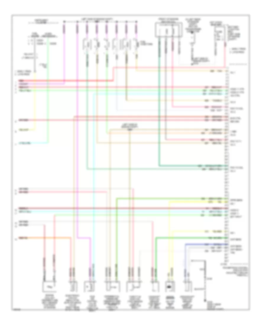
- Fuel tank assembly
- Fuel tank pressure sensor
- Fuel tank pressure transducer sensor
- Fuse 15a
- Fuse 46 15a 30a
- Fuse 5a
- Heated oxygen sensor (ho2s) 11 (on exhaust, pipe of engine)
- Heated oxygen sensor (ho2s) 12 (on exhaust, pipe of engine)
- Heated oxygen sensor (ho2s) 21 (on exhaust, pipe of engine)
- Heated oxygen sensor (ho2s) 22 (on exhaust, pipe of engine)
- Hot at all times
- Hot in run or start
- Inertia fuel shutoff switch (base of right "a" pillar)
- J/c 1 (in battery junction box)
- Late prod
- N r
- Nca
- Red
- Red/pnk
- S100 (vehicle under- body)
- S102
- S103 (left side of engine compt)
- S230
4.0L, Engine Performance Wiring Diagrams (4 of 4) for Ford Explorer 2002
 https://portal-diagnostov.com/license.html
Automotive Electricians Portal FZCO
Automotive Electricians Portal FZCO
https://portal-diagnostov.com/license.html
https://portal-diagnostov.com/license.html
Automotive Electricians Portal FZCO
Automotive Electricians Portal FZCOList of elements for 4.0L, Engine Performance Wiring Diagrams (4 of 4) for Ford Explorer 2002:
- (front of engine) ignition coil
- (in left rear of engine compt) ignition transformer capacitor
- (left side of engine compt) s104
- (left side of engine compt) s105
- (left side of engine compt) s134
- (on top rear of engine)
- 25a
- Battery junction box (left side of engine compt)
- C175c
- C220a
- C220b
- Camshaft position sensor (top front of left cyl head)
- Ckp sens +
- Ckp sens -
- Cmp sens
- Crankshaft position sensor (left front of engine)
- Dfpe sens
- Differential pressure feedback egr (dfpe) sensor (top of throttle body)
- Early prod
- Ect input
- Electronic vacuum regulator (evr) solenoid valve (right rear of cyl head)
- Engine coolant temperature (ect) sensor (top right of engine)
- Evr ctrl
- Fuel gauge
- Fuel injectors
- Fuse 15a
- G105 (right rear side of engine compt)
- Ho2s 11
- Ho2s 11 htr
- Ho2s 21
- Ho2s 21 htr
- Hot in run or start
- Iac ctrl
- Idle air control valve (top of throttle body)
- Inj 1
- Inj 2
- Inj 3
- Inj 4
- Inj 5
- Inj 6
- Instrument cluster
- Knock sensor
- Ks 1
- Late prod
- Micro- processor
- Nca
- Pcm to coil
- Pcm to t1
- Powertrain control module (pcm) (mounted through firewall)
- Red
- Return
- S106
- Tan
- Throttle position (tps) sensor (top of throttle body)
- Tps
- V ref
4.6L
4.6L, Engine Performance Wiring Diagrams (1 of 4) for Ford Explorer 2002
 https://portal-diagnostov.com/license.html
Automotive Electricians Portal FZCO
Automotive Electricians Portal FZCO
https://portal-diagnostov.com/license.html
https://portal-diagnostov.com/license.html
Automotive Electricians Portal FZCO
Automotive Electricians Portal FZCOList of elements for 4.6L, Engine Performance Wiring Diagrams (1 of 4) for Ford Explorer 2002:
- (behind left side of dash) s231
- (center of dash)
- (mounted on master cylinder) brake pressure switch
- (right rear of engine compt)
- (right rear of engine compt) g104
- 15a
- 4wd
- 4wd lo
- A/c rly
- A/c sw
- A/c system
- Ac demand
- Anti-theft system
- Audio unit
- Battery
- Battery junction box (left side of engine compt)
- Brake in
- C117
- C175a
- C201a
- C240a
- Can vent
- Charging system
- Cruise control system
- Cruise set
- Data link connector (behind left side of dash)
- Early prod
- Evap pu
- Evaporative emission (evap) canister vent valve (right center of vehicle)
- F pmp pwr
- Fuse 15a
- Fuse 40a
- Fuse 5a
- G101 (behind left front headlamp)
- G103 (right front of engine compt)
- G104 (right rear of engine)
- G105 (right rear of engine compt)
- Generic electronic module (behind right side of dash)
- Ground
- Hot at all times
- Hot in run or start
- Iat in
- Ign
- Ind ctrl
- Ind input
- J/c 1
- J/c 2
- Late prod
- Maf out
- Mass airflow (maf) sensor (right front of engine compartment)
- Od off
- Passive anti-theft transceiver (on steering column)
- Pcm power diode
- Pcm power relay
- Pgm sig
- Powertrain control module (pcm) (mounted through firewall)
- Pres sw
- Red
- Red/pnk
- Return
- Rly ctrl
- Rx sig
- S116
- S127 (right front of engine compt)
- S129
- S130
- S131
- S132
- S135
- S210
- S211
- Scp bus +
- Scp bus -
- Sens rtn
- Spd ctrl
- Spd sw
- St mtr
- Starting system
- Tank press
- Transmission control system
- Tx sig
- V ref
- Vapor manage- ment valve (left rear of engine compt)
- Vss
- W/ ivd
- W/o ivd
- Windshield wiper motor (left side of engine compt)
4.6L, Engine Performance Wiring Diagrams (2 of 4) for Ford Explorer 2002
 https://portal-diagnostov.com/license.html
Automotive Electricians Portal FZCO
Automotive Electricians Portal FZCO
https://portal-diagnostov.com/license.html
https://portal-diagnostov.com/license.html
Automotive Electricians Portal FZCO
Automotive Electricians Portal FZCOList of elements for 4.6L, Engine Performance Wiring Diagrams (2 of 4) for Ford Explorer 2002:
- (above brake pedal) brake pedal position switch
- Abs control module (left front of engine compt)
- Battery junction box (left side of engine compt)
- C175b
- C270d
- C270h
- Central junction box (behind left side of dash)
- Epc sol
- Fuse 15a
- H2os 12 htr
- H2os 12 in
- H2os 22 htr
- H2os 22 in
- Hot in run or start
- Intermediate shaft speed (iss) sensor (top left side of trans)
- Iss
- J/c 1 (in battery junction box)
- Oss
- Output shaft speed sensor (left rear of trans) (a/t) (top right of trans) (m/t)
- Pcs b
- Pcs c
- Powertrain control module (pcm) (mounted through firewall)
- Press ctrl sol a
- Press ctrl sol b
- Press ctrl sol c
- Red
- Red/pnk
- Redundant pedal switch (under left side of dash)
- S101 (vehicle underbody)
- S120 (left front of engine compt)
- Shift sol a
- Shift sol b
- Shift sol c
- Shift sol d
- Sig rtn
- Ss a
- Ss b
- Ss c
- Ss d
- Tcc sol
- Tft
- Tr1
- Tr2
- Tr3a
- Tr4
- Transmission control switch
- Transmission fluid temperature sensor
- Transmission solenoid body assembly
- Tss
- Turbine shaft speed (tss) sensor (a/t) (top left of trans)
- W/ ivd
- W/o ivd
4.6L, Engine Performance Wiring Diagrams (3 of 4) for Ford Explorer 2002
 https://portal-diagnostov.com/license.html
Automotive Electricians Portal FZCO
Automotive Electricians Portal FZCO
https://portal-diagnostov.com/license.html
https://portal-diagnostov.com/license.html
Automotive Electricians Portal FZCO
Automotive Electricians Portal FZCOList of elements for 4.6L, Engine Performance Wiring Diagrams (3 of 4) for Ford Explorer 2002:
- (behind center
- (left side "a" pillar) g300
- (lower left side of transmission) digital transmission range sensor
- (right "d" pillar) g401
- (right side of eng compt)
- Battery junction box (left side of engine compt)
- C220a
- C220b
- C270f
- Central junction box (behind left side of dash)
- Early prod
- Fuel gauge
- Fuel pump relay
- Fuel pump/ fuel gauge sender
- Fuel tank assembly
- Fuel tank pressure sensor
- Fuse 15a
- Fuse 46 15a 30a
- Fuse 5a
- Heated oxygen sensor (ho2s) 11 (on exhaust, pipe of engine)
- Heated oxygen sensor (ho2s) 12 (on exhaust, pipe of engine)
- Heated oxygen sensor (ho2s) 21 (on exhaust, pipe of engine)
- Heated oxygen sensor (ho2s) 22 (on exhaust, pipe of engine)
- Hot at all times
- Hot in run or start
- Inertia fuel shutoff switch (base of right "a" pillar)
- Instrument cluster
- J/c 1 (in battery junction box)
- Late prod
- Micro- proces- sor
- N r
- Nca
- Of dash) s208
- Red
- Red/pnk
- S100 (vehicle under- body)
- S102
- S103 (left side of engine compt)
- S230
4.6L, Engine Performance Wiring Diagrams (4 of 4) for Ford Explorer 2002
 https://portal-diagnostov.com/license.html
Automotive Electricians Portal FZCO
Automotive Electricians Portal FZCO
https://portal-diagnostov.com/license.html
https://portal-diagnostov.com/license.html
Automotive Electricians Portal FZCO
Automotive Electricians Portal FZCOList of elements for 4.6L, Engine Performance Wiring Diagrams (4 of 4) for Ford Explorer 2002:
- (left side of engine compt) s104
- (left side of engine compt) s105
- (on top rear of engine)
- (right side of eng compt) s108
- Battery junction box (left side of engine compt)
- C175c
- Camshaft position sensor (top front of left cyl head)
- Ckp sens +
- Ckp sens -
- Cmp sens
- Coil on plug
- Cop 1
- Cop 2
- Cop 3
- Cop 4
- Cop 5
- Cop 6
- Cop 7
- Cop 8
- Crankshaft position sensor (left front of engine)
- Cyl input
- Cylinder head temperature sensor (top front of cylinder head)
- Dfpe sens
- Differential pressure feedback egr (dfpe) sensor (top of throttle body)
- Early prod
- Electronic vacuum regulator (evr) solenoid valve (right rear of cyl head)
- Evr ctrl
- Fuel injec- tors
- Fuse 15a 25a
- Ho2s 11
- Ho2s 11 htr
- Ho2s 21
- Ho2s 21 htr
- Hot in run or start
- Iac ctrl
- Idle air control valve (top of throttle body)
- Ignition transformer capacitor 2 (engine compt)
- Inj 1
- Inj 2
- Inj 3
- Inj 4
- Inj 5
- Inj 6
- Inj 7
- Inj 8
- Knock sensor
- Ks 1
- Late prod
- Nca
- Powertrain control module (pcm) (mounted through firewall)
- Red
- Return
- S109 (right side of engine compt)
- Tan
- Tan/red
- Throttle position (tps) sensor (top of throttle body)
- Tps
- V ref

 Čeština
 Dansk
Dansk Deutsch
 Ελληνικά
 English
 English
 Español
 Suomi
Suomi Français
 Français
 עברית
עברית Hrvatski
 Magyar
 Italiano
 日本語
日本語 Nederlands
 Polski
 Português
 Português
 Română
 Русский
 Slovenčina
 Slovenščina
 Svenska
 Türkçe
 中文 (中国)
