STARTING/CHARGING
Charging Wiring Diagram for Chevrolet Uplander LT 2006
 https://portal-diagnostov.com/license.html
Automotive Electricians Portal FZCO
Automotive Electricians Portal FZCO
https://portal-diagnostov.com/license.html
https://portal-diagnostov.com/license.html
Automotive Electricians Portal FZCO
Automotive Electricians Portal FZCO
List of elements for Charging Wiring Diagram for Chevrolet Uplander LT 2006:
- 3.5l
- 3.9l
- Battery
- Battery current sensor (right front of engine comt, near battery)
- Battery ind
- Body control module (bcm) (below left side of dash, left of steering column)
- Class 2 serial data
- Clstr/ hvac fuse 8 10a
- Current sens sig
- Current sense
- G102 (right side of engine compt on frame rail, right of engine fuse block)
- G115 (at engine to transmission stud nearest starter below g113)
- Gen field duty cycle sign
- Gen turn on sig
- Generator
- Ground
- Hot at all times
- I/p dimming voltage ref
- I/p fuse block (right side of dash, behind access panel)
- Ign
- Ign 1 volt
- Instrument panel cluster
- Interior lights system
- Low ref
- Power distribution system
- Powertrain control module (pcm) (3.5l) engine control module (ecm) (3.9l) (3.5l: left side of engine compt, in air cleaner assembly)
- Red
- S257 (in dash harness, 8.5 cm from breakout for ipc toward right side of dash)
- Sp205 (on dash harness near headlamp switch connector, behind left dash access panel)
- Starter motor
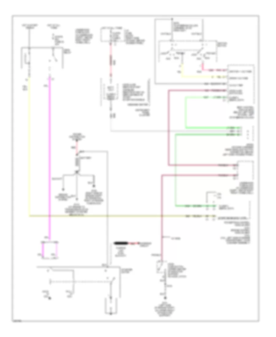
Starting Wiring Diagram for Chevrolet Uplander LT 2006
 https://portal-diagnostov.com/license.html
Automotive Electricians Portal FZCO
Automotive Electricians Portal FZCO
https://portal-diagnostov.com/license.html
https://portal-diagnostov.com/license.html
Automotive Electricians Portal FZCO
Automotive Electricians Portal FZCOList of elements for Starting Wiring Diagram for Chevrolet Uplander LT 2006:
- (w/ rke)
- -hood ajar -remote start disabled -remote start on -service remote start -starting disable
- 12-volt ref
- 3.5l
- 3.9l
- Acc
- Batt volt
- Battery
- Body control module (bcm) (below left side of dash, left of steering column)
- Charging circuit
- Class 2 serial data
- Clstr/ hvac fuse 8 10a
- Crank voltage
- Crnk relay
- G101 (left side of engine compt, on upper front of radiator support)
- G102 (right side of engine compt on frame rail, right of engine fuse block)
- G115 (at engine to transmission stud nearest starter, below g113)
- Ground distribution system
- Hold- in coil
- Hood ajar switch (upper center of radiator support, on hood latch)
- Hood ajar switch sig
- Hot at all times
- Hot in start or run
- I/p fuse block (right side of dash, behind access panel)
- Ignition 1 voltage
- Ignition switch
- Instrument panel cluster
- Lock
- Message center
- Pnk
- Power distribution system
- Powertrain control module (pcm) (3.5l) engine control module (ecm) (3.9l) (3.5l: left side of engine compartment, in air cleaner assembly)
- Pull- in coil
- Red
- Run
- S103
- S279 (in steering column harness, 20 cm from c201)
- Sp205 (on dash harness near headlamp switch connector, behind left dash access panel)
- Start
- Start enable rly ctrl
- Starter motor
- Strtr sol fuse 30 40a
- Underhood fuse block (in underhood compt, above right front wheelwell)

 Čeština
 Dansk
Dansk Deutsch
 Ελληνικά
 English
 English
 Español
 Suomi
Suomi Français
 Français
 עברית
עברית Hrvatski
 Magyar
 Italiano
 日本語
日本語 Nederlands
 Polski
 Português
 Português
 Română
 Русский
 Slovenčina
 Slovenščina
 Svenska
 Türkçe
 中文 (中国)
