ANTI-LOCK BRAKES
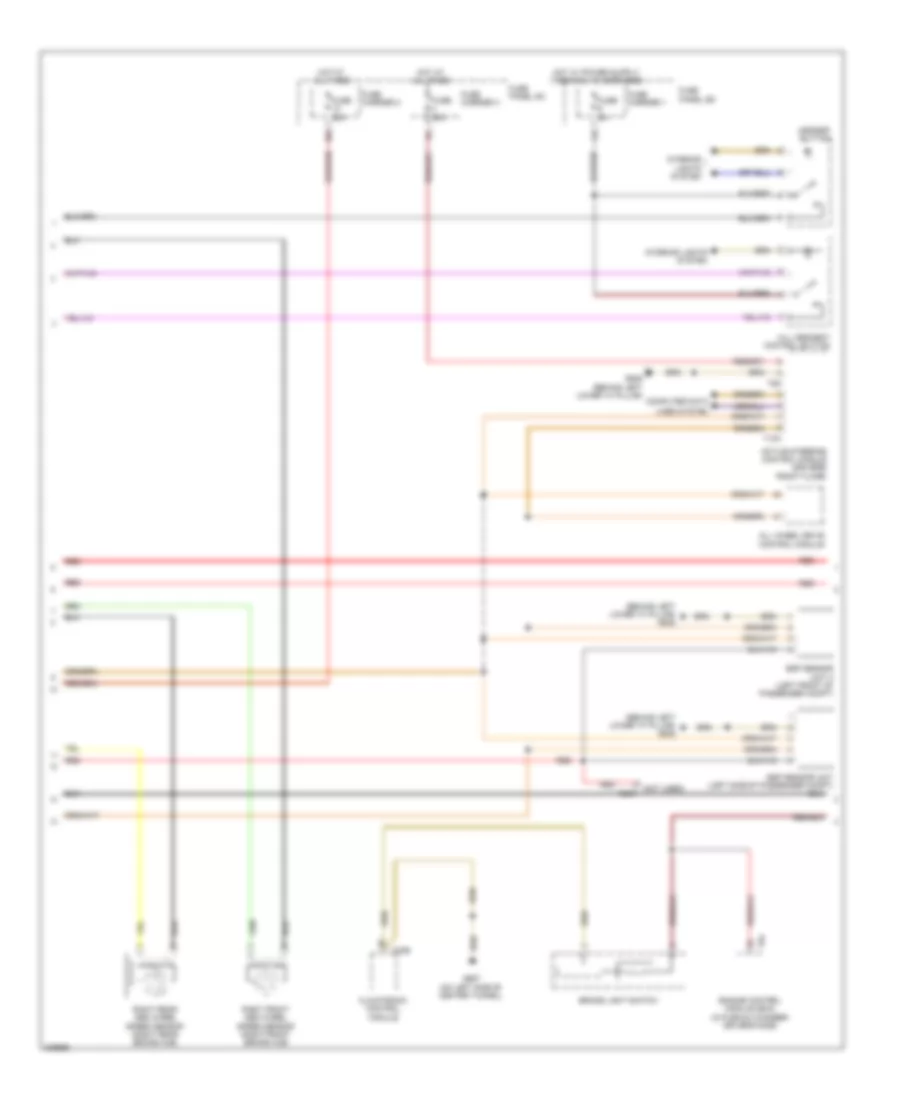
Anti-lock Brakes Wiring Diagram (1 of 3) for Audi Q5 Quattro 2009
 https://portal-diagnostov.com/license.html
Automotive Electricians Portal FZCO
Automotive Electricians Portal FZCO
https://portal-diagnostov.com/license.html
https://portal-diagnostov.com/license.html
Automotive Electricians Portal FZCO
Automotive Electricians Portal FZCO
List of elements for Anti-lock Brakes Wiring Diagram (1 of 3) for Audi Q5 Quattro 2009:
- (left side of engine compt) abs control module
- (not used)
- 40a
- Abs control module fuse 1
- Abs hydraulic pump
- Abs inlet left rear
- Abs outlet left rear
- Auto hold button
- Computer data lines system
- Driving dynamics regulation high pressure switch valve 2
- Electro-mechanical parking brake button
- Fuse 10a
- Fuse 110a
- Fuse 5a
- Fuse carrier 2
- Fuse carrier 4
- Fuse panel sc
- G671 (on long member near front left wheel housing)
- Hot at all times
- Left front abs inlet valve
- Left front abs outlet valve
- Left front abs wheel speed sensor (left front brake hub)
- Left rear abs wheel speed sensor (left rear brake hub)
- Main fuse panel sa
- Pressure switch valve 1
- Red
- Regulation high driving dynamics
- Regulation switch driving dynamics
- Relay/fuse carrier luggage compartment sf
- Right front abs inlet valve
- Right front abs outlet valve
- Right rear abs inlet valve
- Right rear abs outlet valve
- T17d
- T2ct
- Valve
- Valve 1
- Valve 2
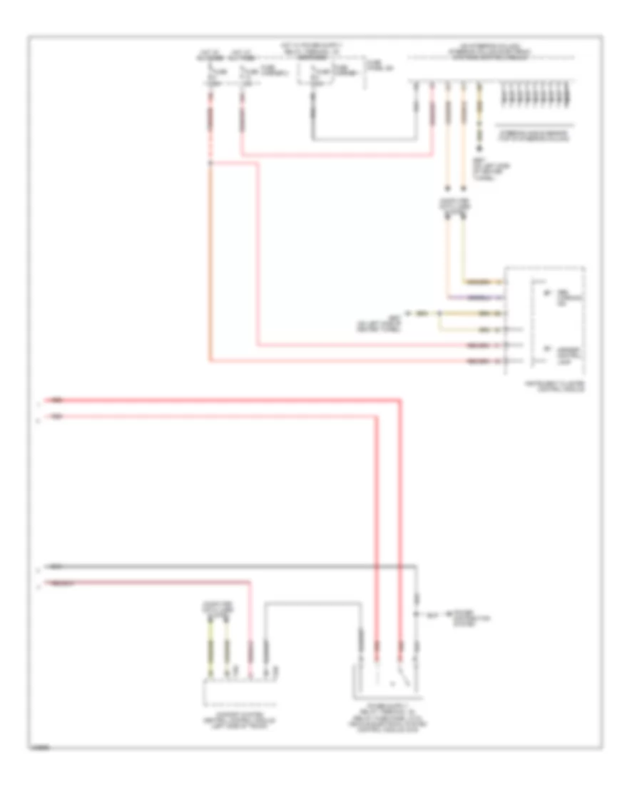
Anti-lock Brakes Wiring Diagram (2 of 3) for Audi Q5 Quattro 2009
List of elements for Anti-lock Brakes Wiring Diagram (2 of 3) for Audi Q5 Quattro 2009:
- (behind left lower "a" pillar) g639
- (not used) t2ct
- 10a
- Active steering control module (driver's front floor)
- All wheel drive control module
- Asr/esp button
- Brake light switch
- Climatronic control module
- Computer data
- Engine control module (ecm) (in plenum chamber driver's side)
- Esp sensor unit (left side of passenger compt)
- Esp sensor unit 2 (left front of passenger compt)
- Fuse 25a
- Fuse 35a
- Fuse 5a
- Fuse carrier 1
- Fuse carrier 2
- Fuse carrier 3
- Fuse panel sc
- Fuse panel sd
- G639 (behind left lower "a" pillar)
- G687 (on left side of center tunnel)
- Hill descent control button
- Hot at all times
- Interior lights system
- Lines system
- Red
- Right front abs wheel speed sensor (right front brake hub)
- Right rear abs wheel speed sensor (right rear brake hub)
- T10h
- T20e
- T5d
- T94
Anti-lock Brakes Wiring Diagram (3 of 3) for Audi Q5 Quattro 2009
List of elements for Anti-lock Brakes Wiring Diagram (3 of 3) for Audi Q5 Quattro 2009:
- (on steering column) steering column electronic systems control module
- Abs warning ind
- Asr/esp control lamp
- Comfort system central control module (left side of trunk)
- Computer data lines system
- Fuse 5a
- Fuse carrier 1
- Fuse carrier 2
- Fuse panel sd
- G687 (on left side of center tunnel)
- Hot at all times
- Instrument cluster control module
- Nca
- Power distribution system
- Red
- Steering angle sensor (top of steering column)
- T32c
- T32d

 Čeština
 Dansk
Dansk Deutsch
 Ελληνικά
 English
 English
 Español
 Suomi
Suomi Français
 Français
 עברית
עברית Hrvatski
 Magyar
 Italiano
 日本語
日本語 한국어
한국어 Polski
 Português
 Português
 Română
 Русский
 Slovenčina
 Slovenščina
 Svenska
 Türkçe
 中文 (中国)