ANTI-LOCK BRAKES
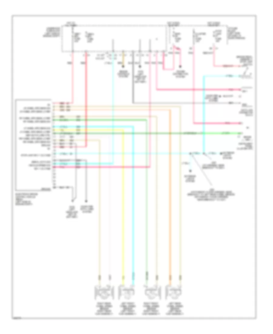
Anti-lock Brakes Wiring Diagram for Pontiac G3 2009
List of elements for Anti-lock Brakes Wiring Diagram for Pontiac G3 2009:
- (brake pedal assembly) stop lamp switch
- Abs ind failure ctrl
- Abs-1 ef2 fuse 40a
- Abs-2 ef3 fuse 50a
- Brake ind
- Cluster f3 fuse 10a
- Computer data lines system
- Data link connector (dlc) 2
- Electronic brake control module (ebcm) (left side of engine compt)
- Ems1 f6 fuse 15a
- Engine controls system
- Exterior lights system
- G102 (left headlamp, left of battery)
- Gnd
- Ground
- Hot at all times
- Hot in run or start
- I/p fuse block (left side of dash, in door opening)
- Ign 1
- Ign 1 voltage
- Instrument panel cluster (ipc)
- J223 (i/p harness, near breakout to g201)
- J320 (hatchback: floor harness, near breakout to left rear wheel sensor) (notchback: floor harness, near breakout to x401)
- Left front wheel speed sensor (left front hub assembly)
- Left rear wheel speed sensor (left rear hub assembly)
- Lf wheel spd sens lo ref
- Lf wheel spd sens sig
- Lr wheel spd sens lo ref
- Lr wheel spd sens sig
- Pnk
- Power distribution system
- Red
- Rf wheel spd sens lo ref
- Rf wheel spd sens sig
- Right front wheel speed sensor (right front hub assembly)
- Right rear wheel speed sensor (right rear hub assembly)
- Rr wheel spd sens lo ref
- Rr wheel spd sens sig
- Serial data sig
- Stop lamp f7 fuse 15a
- Stop lamp sply voltage
- Underhood fuse block (left side of engine compt)
- Vehicle speed sig
- W/ ldt
- W/o ldt
 Čeština
 Dansk
Dansk Deutsch
 Ελληνικά
 English
 English
 Español
 Suomi
Suomi Français
 Français
 עברית
עברית Hrvatski
 Magyar
 Italiano
 日本語
日本語 한국어
한국어 Polski
 Português
 Português
 Română
 Русский
 Slovenčina
 Slovenščina
 Svenska
 Türkçe
 中文 (中国)
 Nederlands