DEFOGGERS
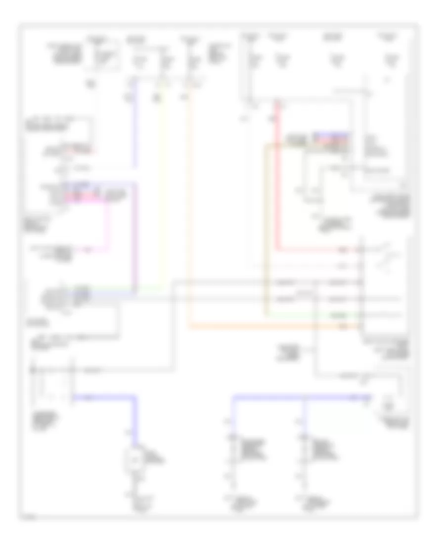
Defoggers Wiring Diagram for Infiniti G35 2003
List of elements for Defoggers Wiring Diagram for Infiniti G35 2003:
- (behind instrument cluster) m30
- (behind right side of dash) m66
- (on left "c" pillar) b242
- (on right side of engine compartment) e17
- 15a
- A/c & audio controller
- B241
- B301
- Battery
- Body control module (behind left kick panel)
- Can-h
- Can-l
- Computer data lines system
- Condenser (rear window defogger) (at right "c" pillar)
- Cpu
- Data link connector (partial) (lower left side of dash)
- Driver side door mirror defogger (if equipped)
- E101
- E102
- E105
- E43 (on left front side of engine compartment)
- Fuse 10a
- Fuse 15a
- Fuse 20a
- Fuse 8 10a
- Fuse block (j/b) (behind left kick panel)
- Fuse, fusible link & relay box (at right rear side of engine compartment)
- Fusible link f 50a
- Gnd (power)
- Gnd (signal)
- Ground
- Hot at all times
- Hot in on or start
- If equipped (optional mirror defoggers)
- Ig+
- Ign
- Ignition
- Intelligent power distribution module engine room (at right rear corner of engine compartment)
- K-line
- M30 (behind instrument cluster)
- M38
- Passenger side door mirror defogger (if equipped)
- Rear window defogger
- Rear window defogger relay (right rear panel of luggage compartment)
- Red
- Rr def f/b
- Rr def on
- Rr def rly
- Rr def sw
 Čeština
 Dansk
Dansk Deutsch
 Ελληνικά
 English
 English
 Español
 Suomi
Suomi Français
 Français
 עברית
עברית Hrvatski
 Magyar
 Italiano
 日本語
日本語 한국어
한국어 Nederlands
 Português
 Português
 Română
 Русский
 Slovenčina
 Slovenščina
 Svenska
 Türkçe
 中文 (中国)
 Polski