ANTI-LOCK BRAKES
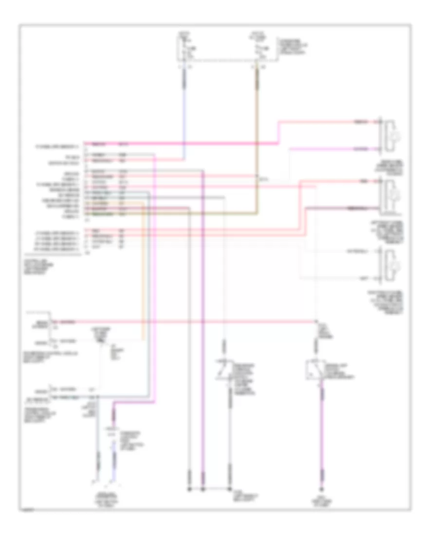
Anti-lock Brake Wiring Diagrams for Dodge Pickup R1500 2002
List of elements for Anti-lock Brake Wiring Diagrams for Dodge Pickup R1500 2002:
- (left bottom of dash)
- (left rear of eng compt) s117
- A/t except 5.9l only
- A10
- A20
- B113
- B114
- Brake lamp switch (on brake pedal bracket)
- Brake sw sens
- Brake sw sense
- Controller anti-lock brake (left fender side shield)
- D25
- Data link connector
- Diagnostic junction port (left bottom of dash)
- Fuse 10a
- Fuse 40a
- Fuse b (+)
- G106 (left rear of eng compt)
- G201 (right side of dash)
- Ground
- Hot at all times
- Hot in run
- Ignition sw (run)
- Integrated power module (left front of eng compt)
- K29
- Left front wheel speed sensor (w/ all wheel abs) (on left front steering hub assembly)
- Lf wheel spd sensor (+)
- Lf wheel spd sensor (-)
- Pci bus
- Powertrain control module (right rear of eng compt)
- R wheel spd sensor (+)
- R wheel spd sensor (-)
- Rear wheel speed sensor (in differential housing)
- Red
- Red brake warn ind
- Red brake warning indicator switch (on brake master cylinder reservoir)
- Rf wheel spd sensor (+)
- Rf wheel spd sensor (-)
- Right front wheel speed sensor (w/ all wheel abs) (on right front steering hub assembly)
- S114
- S115 (left of eng compt)
- S121 (left front fender)
- Sci receive
- Transmission control module (right rear of eng compt)
- Vehicle speed sig
- Vss sig
- Z101
- Z102
 Čeština
 Dansk
Dansk Deutsch
 Ελληνικά
 English
 English
 Español
 Suomi
Suomi Français
 Français
 עברית
עברית Hrvatski
 Magyar
 Italiano
 日本語
日本語 한국어
한국어 Nederlands
 Português
 Português
 Română
 Русский
 Slovenčina
 Slovenščina
 Svenska
 Türkçe
 中文 (中国)
 Polski