CRUISE CONTROL
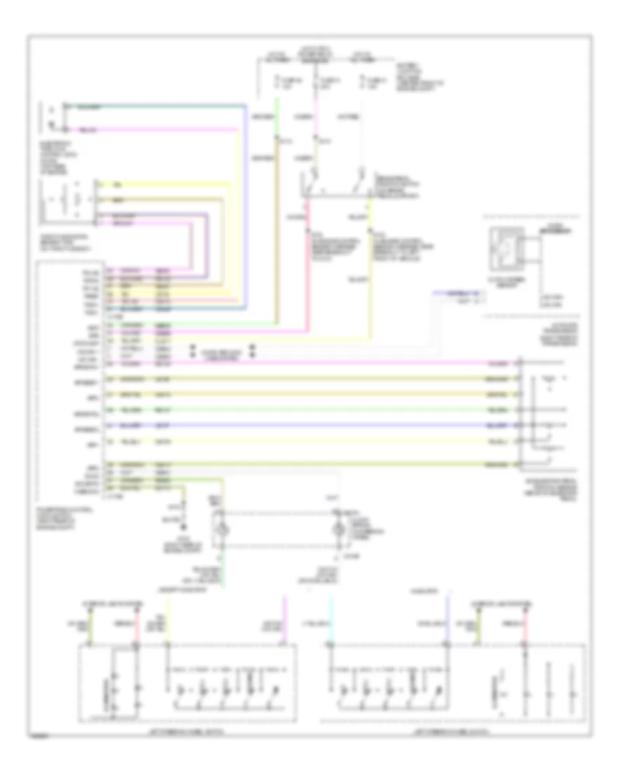
Cruise Control Wiring Diagram for Ford Expedition 2008
List of elements for Cruise Control Wiring Diagram for Ford Expedition 2008:
- (right rear of transmission)
- Accelerator pedal position sensor (above accelerator pedal)
- App1
- App2
- App3
- Appsref1
- Appsref2
- Appsrtn1
- Appsrtn2
- Automatic transmission
- Battery junction box (bjb) (center front of engine compt)
- Bps
- Brake pedal position switch (on brake pedal support)
- C175b
- C175e
- C218a
- C218b
- Case gnd
- Ce105
- Ce412
- Ce414
- Ce415
- Ce426
- Ces09
- Clock spring (in steering wheel)
- Cls17
- Computer data lines system
- Electronic throttle control (etc) motor (top rear of engine)
- Except navigator
- Fuse 31 15a
- Fuse 36 10a
- Fuse 74 20a
- G108 (right rear of engine compt)
- Gd113
- Hot at all times
- Hot w/ pcm power relay energized
- Hs can +
- Hs can -
- Hs can+
- Hs can-
- Illumination
- Interior lights system
- Le134
- Le136
- Le137
- Left steering wheel switch
- Micro processor
- Navigator
- Off
- Output speed sensor
- Powertrain control module (pcm) (right rear of engine compt)
- Re134
- Re136
- Re137
- Res08
- Resume
- S103
- S112
- S115
- S124 (in engine control sensor harness, near breakout to left front of vehicle)
- S133 (in engine control sensor harness, near breakout to c212)
- Sbb36
- Sccs
- Sccsrtn
- Set (+)
- Set (-)
- Stoplamp
- Tacm+
- Tacm-
- Throttle position sensor (tps) (on throttle body)
- Tp1 ns
- Tp2 ps
- Tpref
- Tprtn
- Vbat
- Vdb04
- Vdb05
- Ve818
- Ve819
- Ves10
 Čeština
 Dansk
Dansk Deutsch
 Ελληνικά
 English
 English
 Español
 Suomi
Suomi Français
 Français
 עברית
עברית Hrvatski
 Magyar
 Italiano
 日本語
日本語 한국어
한국어 Nederlands
 Português
 Português
 Română
 Русский
 Slovenčina
 Slovenščina
 Svenska
 Türkçe
 中文 (中国)
 Polski