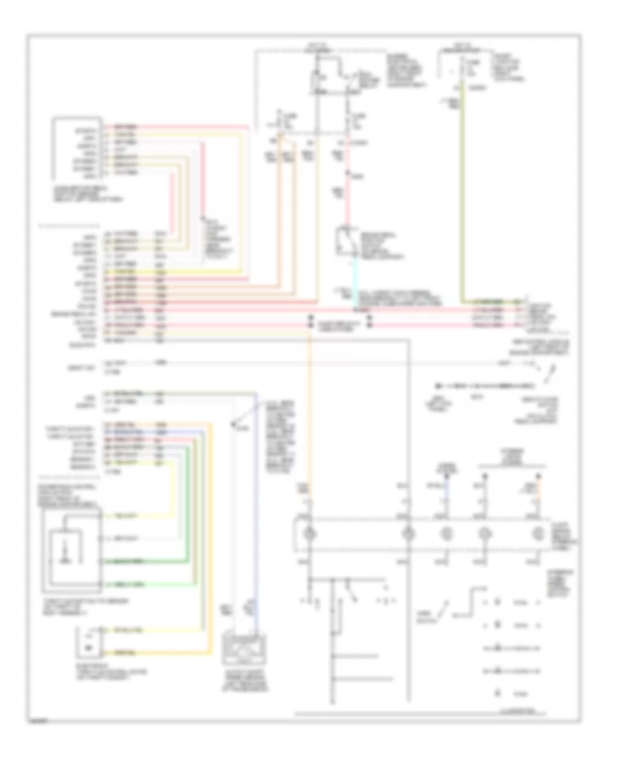
CRUISE CONTROL
Cruise Control Wiring Diagram for Ford Mustang 2007
List of elements for Cruise Control Wiring Diagram for Ford Mustang 2007:
- (4.0l: near breakout to heated oxygen sensor 12) (4.6l: near breakout to heated oxygen sensor 11) (5.4l: near breakout to c1164)
- (5.4l: in body main harness, near breakout to left front channel subwoofer amplifier) s227
- Abs control module (left front of engine compartment)
- Accelerator pedal position sensor (below left side of dash)
- App1
- App2
- App3
- Brake pedal position switch (on brake pedal support)
- Brake pedal sw
- Bussed electrical center (bec) (right front of engine compartment)
- C1035a c2
- C175b
- C175e
- C175t
- C2280h
- Clock spring (below steering wheel)
- Computer data lines system
- Deact sw
- Deactivator switch (m/t) (on clutch pedal support)
- Electronic throttle control motor (on throttle body)
- Etc ref
- Etc rtn
- Etcref1
- Etcref2
- Etcrtn
- Fuse 10a
- Fuse 15a
- G204 (left kick panel)
- Horn
- Horns system
- Hot at all times
- Hot in run or start
- Hs can+
- Hs can-
- Ignition brake pedal sw hs can+
- Illumination
- Interior lights system
- Nca
- Oss
- Output shaft speed sensor (left rear side of transmission)
- Pcm power relay
- Pcm rc
- Powertrain control module (pcm) (right front of engine compartment)
- S106
- S212 (in body main harness, near breakout to c211)
- S215
- S225
- Sccs
- Sccs rtn
- Sensor 1
- Sensor 2
- Sigrtn
- Smart junction box (sjb) (right kick panel)
- Steering wheel/ speed control switch
- Switch
- Throttle motor +
- Throttle motor -
- Throttle position (tp) sensor (on throttle body assembly)
- Vpwr
 Čeština
 Dansk
Dansk Deutsch
 Ελληνικά
 English
 English
 Español
 Suomi
Suomi Français
 Français
 עברית
עברית Hrvatski
 Magyar
 Italiano
 日本語
日本語 한국어
한국어 Nederlands
 Português
 Português
 Română
 Русский
 Slovenčina
 Slovenščina
 Svenska
 Türkçe
 中文 (中国)
 Polski