POWER DISTRIBUTION
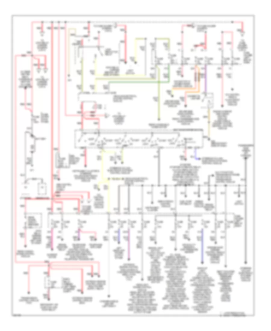
Power Distribution Wiring Diagram, with Convertible (1 of 2) for Audi A4 2005

List of elements for Power Distribution Wiring Diagram, with Convertible (1 of 2) for Audi A4 2005:
- 10a
- 16a
- 17a
- 22a
- 243a
- 30a
- 31a
- 33a
- 36a
- 37a
- 38a
- 4.2l
- 50b
- 86s
- 9-pin relay carrier
- A/c control head
- Abs control module (w/ edl)
- Abs control module fuse 1
- Acc
- Air quality sensor & high pressure sensor
- Airbag control module
- Back-up light switch, automatic day/night interior mirror, data link connector (dlc), shift lock solenoid, multi-function transmission range (tr) switch, transmission control module & park/neutral position relay
- Battery
- Brake booster relay
- Brake light switch, clutch vacuum vent valve switch, abs control module (w/ edl) & anti-slip control switch
- Cigarette lighter
- Conver- tible top fuse 40a
- Convertible top control module
- Convertible top operation hydraulic unit
- Driver side door control module
- E-box relay carrier
- Fuel pump (fp) relay
- Fuse 10a
- Fuse 150a
- Fuse 15a
- Fuse 25a
- Fuse 30a
- Fuse 40a
- Fuse 50a
- Fuse 5a
- Fuse holder
- Fuse strip (main fuse)
- G11
- G33
- Garage door opener control head & garage door opener control module
- Generator
- Headlight adjuster & headlight range control module
- Ignition/starter switch
- Instrument cluster
- Instrument cluster & steering column electronic systems control module
- Light switch
- Load reduction relay
- Lock
- Motronic engine control module (ecm)
- Nca
- Off
- Oil level thermal sensor, board computer function selector switch ii, tiptronic switch & control module for navigation w/ cd-mechanism
- On off
- Passenger side door control module
- Radar interior monitoring control module 1 & 2, alarm horn & comfort system central control module
- Red
- Red b
- Secondary air injection (air) pump relay
- Servotronic control module
- Start
- Starter
- Starter, starter locking relay (clutch pedal switch), starter interlock alarm system relay & park/neutral position relay
- Steering column electronic systems control module
- T10b
- T32b
- Telephone amplifier
- Telephone transceiver
- Tire pressure monitoring control module
- To 4-pin relay carrier (diagram 2 of 2)
- To fuse holder (diagram 2 of 2)
- Transmission control module (tcm)
- Vehicle electrical system control module
- Washer nozzle heater (left/right)
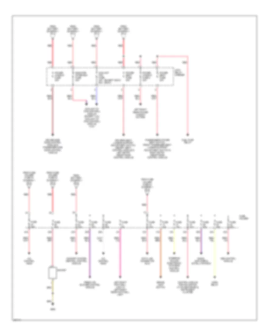
Power Distribution Wiring Diagram, with Convertible (2 of 2) for Audi A4 2005
List of elements for Power Distribution Wiring Diagram, with Convertible (2 of 2) for Audi A4 2005:
- (except 600w) (600w)
- 12a
- 13a
- 14a
- 15a
- 24a
- 25a
- 26a
- 35a
- 39a
- 4-pin relay carrier
- 40a
- 42a
- 44a
- A/c control head
- Abs control module
- Brake light switch
- Comfort system central control module
- Control module for navigation w/ cd mechanism & instrument cluster
- Coolant fan fuse 40a 60a
- Coolant fc (fan control) module (4.2l)
- Coolant fc (fan control) module (except 4.2l)
- Data link connector (dlc)
- Driver side door control module & passenger side door control module
- Driver's seat lumbar support adjustment switch, memory seat control module & left entry assistance control module
- Fresh air blower control module
- From battery (diagram 1 of 2)
- From fuse holder fuse 30 (diagram 1 of 2)
- From fuse holder fuse 33 (diagram 1 of 2)
- Fuel pump relay
- Fuse 10a
- Fuse 20a
- Fuse 25a
- Fuse 30a
- Fuse 5a
- Fuse holder
- G663
- Horn relay
- Left/right footwell light & left/right rear footwell light
- Left/right rear power window motors
- Passenger's power seat switch, front passenger seat lumbar support adjustment switch & right entry assistance control module
- Power seat fuse 30a
- Power window fuse 2 30a
- Power window fuse 30a
- Radiator after run fuse 40a
- Radio, amplifier & satellite radio
- Red
- Socket
- Steering column electronic systems control module
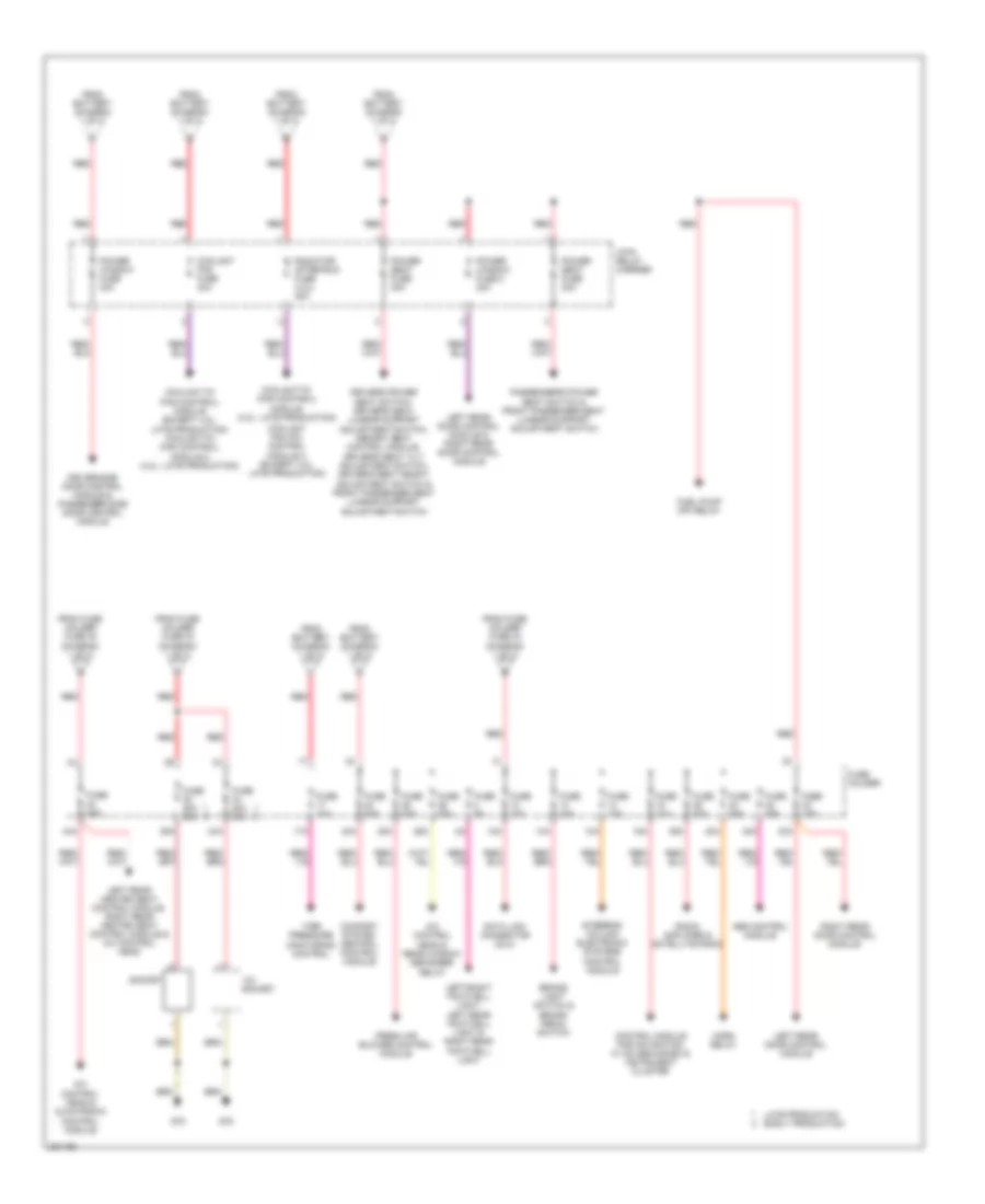
Power Distribution Wiring Diagram, without Convertible (1 of 2) for Audi A4 2005
List of elements for Power Distribution Wiring Diagram, without Convertible (1 of 2) for Audi A4 2005:
- (diagram 2 of 2)
- (w/ rear heated seat) windshield heating voltage converter
- 10a
- 11a
- 16a
- 18a
- 22a
- 243a
- 30a
- 31a
- 33a
- 36a
- 37a
- 38a
- 50b
- 86s
- 9-pin relay carrier (behind left side of dash)
- A/c control head & climate control module
- A/c control head & climatronic control module
- Abs control module (w/edl)
- Abs control module fuse 1
- Acc
- Air quality sensor & high pressure sensor
- Airbag control module
- Back-up light switch, data link connector (dlc), shift lock solenoid, multi-function transmission range (tr) switch, transmission control module, park/neutral position relay, automatic day/ night interior mirror & (late production) mass air flow sensor
- Battery
- Brake booster relay
- Brake light switch, clutch vacuum vent valve switch, abs control module (w/ edl), anti-slip control switch, esp-sensor & brake pedal switch
- Cigarette lighter
- Driver side door control module
- Driver side door control module & front passenger side door control module
- E-box relay carrier (left rear of engine compt)
- Fuel pump (fp) relay
- Fuse 10a
- Fuse 150a
- Fuse 15a
- Fuse 20a
- Fuse 25a 30a
- Fuse 30a
- Fuse 40a
- Fuse 40a 50a
- Fuse 5a
- Fuse holder (left end of dash)
- Fuse strip (main fuse)
- G11
- G33 (behind right side of dash)
- G41
- Garage door opener control head & garage door opener control module
- Generator
- Headlight range control module, headlight adjuster, left headlight beam adjusting motor, right headlight beam adjusting motor, head lamp range/corning lamp control module & right headlight power output stage
- Ignition/starter switch
- Instrument cluster
- Instrument cluster & steering column electronic systems control module
- Late production early production
- Left headlamp power output stage
- Light switch
- Load reduction relay
- Lock
- Motronic engine control module (ecm)
- Motronic engine control module (ecm) & wastegate bypass regulator valve (1.8l)
- Multi-function transmission range (tr) switch & transmission control module
- Navigation w/ cd-mechanism control module
- Nca
- Off
- Oil level thermal sensor, telephone/telematic control module, board computer function selector switch ii, tiptronic switch, rear window shade switch, telephone control module for operating electronics, control module for navigation w/ cd-mechanism, left rear heated seat control module, oil pressure switch & right rear heated seat control module
- On off
- Passenger's side airbag off warning light
- Radar interior monitoring control module, alarm horn & comfort system central control module
- Rear shade circuit breaker 10a
- Rear window shade control module
- Rear windshield wiper motor
- Red
- Red b
- Seat occupied recognition pressure sensor & front passenger's airbag disabled indicator lamp air bag control module
- Secondary air injection (air) pump relay
- Servotronic control module
- Start
- Starter
- Starter, starter interlock relay, clutch pedal switch, starter interlock alarm system relay, starter lock/clutch pedal switch relay & park/neutral position relay
- Steering column electronic systems control module
- Sunroof motor
- T10b
- T10b t10b
- T32b
- Telephone amplifier
- Telephone/ telematic control module, telephone control module for operating electronics & telephone transceiver
- To 4-pin relay carrier (diagram 2 of 2)
- To fuse holder (diagram 2 of 2)
- To fuse holder j
- Transmission control module (tcm)
- Vehicle electrical system control module
- Washer nozzle heater (left/right)
Power Distribution Wiring Diagram, without Convertible (2 of 2) for Audi A4 2005
List of elements for Power Distribution Wiring Diagram, without Convertible (2 of 2) for Audi A4 2005:
- 12a
- 12v socket
- 13a
- 14a
- 15a
- 17a
- 23a
- 24a
- 25a
- 26a
- 34a
- 35a
- 39a
- 4-pin relay carrier
- 40a
- 42a
- 44a
- A/c control head & climatronic control module
- A/c control head & rear window defogger relay
- Abs control module
- Brake light switch & brake pedal switch
- Comfort system central control module
- Control module for navigation w/ cd mechanism & instrument cluster
- Coolant fan (fc) control module 2 (except 4.2l: late production)
- Coolant fan fuse 40a
- Coolant fc (fan control) module (4.2l: late production)
- Coolant fc (fan control) module (except 4.2l: late production) coolant fc (fan control) module 2 (4.2l: late production)
- Data link connector (dlc)
- Driver side door control module & passenger side door control module
- Driver's power seat switch, driver's seat lumbar support adjustment switch, memory seat control module, driver's seat tilt adjustment switch, driver's seat height adjustment switch & front passenger seat lumbar support adjustment switch
- Fresh air blower control module
- From battery (diagram 1 of 2)
- From fuse holder fuse 30 (diagram 1 of 2)
- From fuse holder fuse 33 (diagram 1 of 2)
- Fuel pump (fp) relay
- Fuse 10a
- Fuse 15a
- Fuse 20a
- Fuse 20a 30a
- Fuse 25a
- Fuse 30a
- Fuse 5a
- Fuse holder
- G78
- Horn relay
- Late production early production
- Left rear door control module
- Left rear door control module & right rear door control module
- Left rear heated seat control module, right rear heated seat control module & a/c control head
- Left/right footwell light, left rear footwell light & right rear footwell light
- Passenger's power seat switch & front passenger seat lumbar support adjustment switch
- Power seat fuse 30a
- Power window fuse 2 30a
- Power window fuse 30a
- Radiator after-run fuse (4.2l) 40a
- Radio amplifier & satellite radio
- Red
- Right rear door control module
- Socket
- Steering column electronic systems control module
- Tire pressure monitoring control