POWER DISTRIBUTION
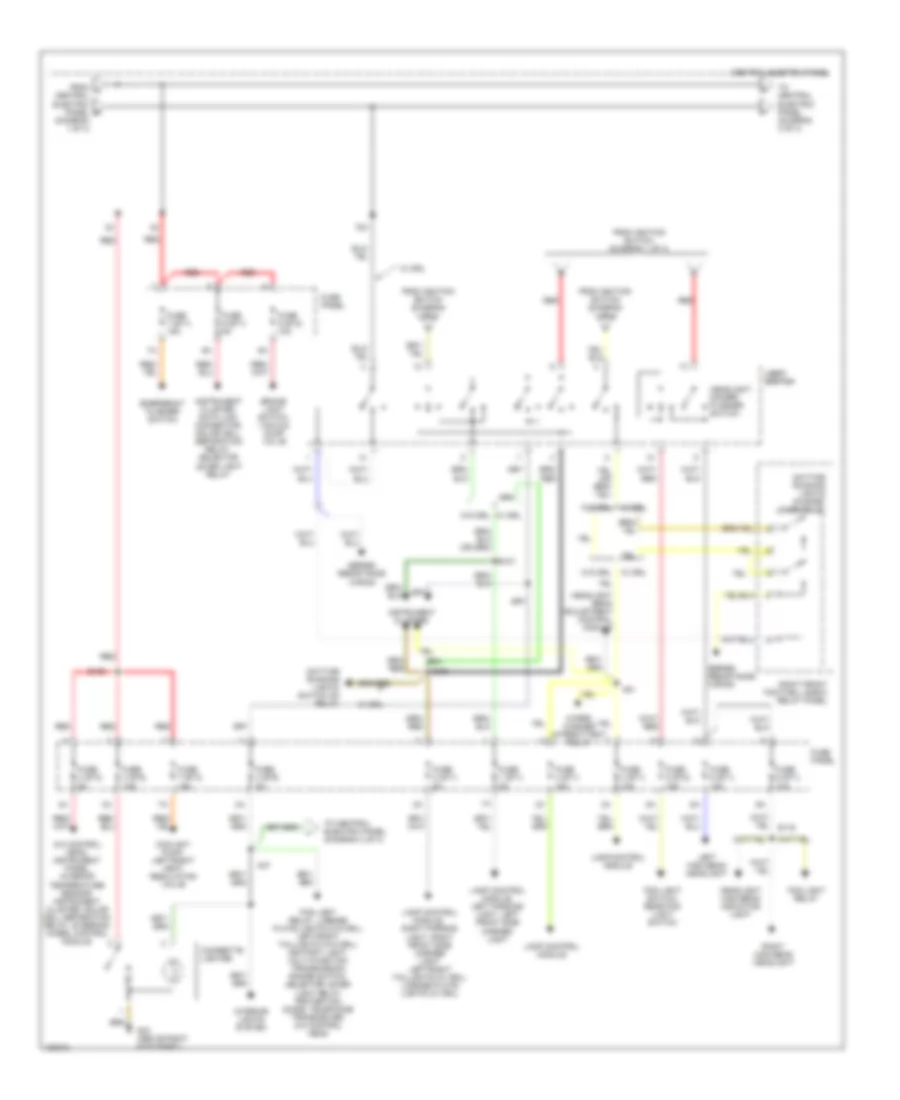
Power Distribution Wiring Diagram (1 of 4) for Audi A8 1997

List of elements for Power Distribution Wiring Diagram (1 of 4) for Audi A8 1997:
- 1998,
- 50b
- 86s
- A22
- Abs control module
- Abs control module (1998-99 quattro)
- Abs hydraulic unit
- Amplifier, left/right rear woofer, power antenna, radio
- Battery
- Central electric panel
- Central locking/ alarm system/ interior light delay control module
- Connector tv1
- Connector tv2
- D50/a32
- Daytime running lights switch on relay
- Dual horn relay
- Dual horns
- E20/a32
- Evaporative emission canister purge regulator valve, intake change-over valve, fuel injector air control valve, leak detection pump
- Fuse 15a
- Fuse 20a
- Fuse 25a
- Fuse 50a
- Fuse 8 (st1) 15a
- Fuse 9 (st4) 5a
- Fuse panel
- G43 (above right kick panel)
- Ignition switch
- Instrument cluster, central locking/ alarm system/ interior light delay control module, radio, steering column/belt height control module
- Key-in ignition switch
- Left/right rear head rest adjustment switch, left/right rear head rest lower relay, left/right rear seat lumbar support height adjustment switch
- Left/right rear seat regulating switch
- Load reduction relay
- Motronic engine control module
- Motronic engine control module, fuel injectors
- Off
- Plenum chamber e-box relay & fuse panel
- Red
- Relay & fuse panel
- Run
- S1/
- S1/ 30ah
- S1/ 87h
- S1/50z
- S4/50z
- S4/a
- S4/b
- S6/50a
- Start
- Starter
- Starting interlock relay
- Steering wheel control module
- Telephone transceiver
- To central electric panel (diagram 2 of 4)
- To fuse 6 (st3) (diagram 3 of 4)
- To light switch (diagram 2 of 4)
- Transmission control module
- Voltage regulator/ generator
- Voltage regulator/ generator, instrument cluster
- Wiper/washer intermittent relay
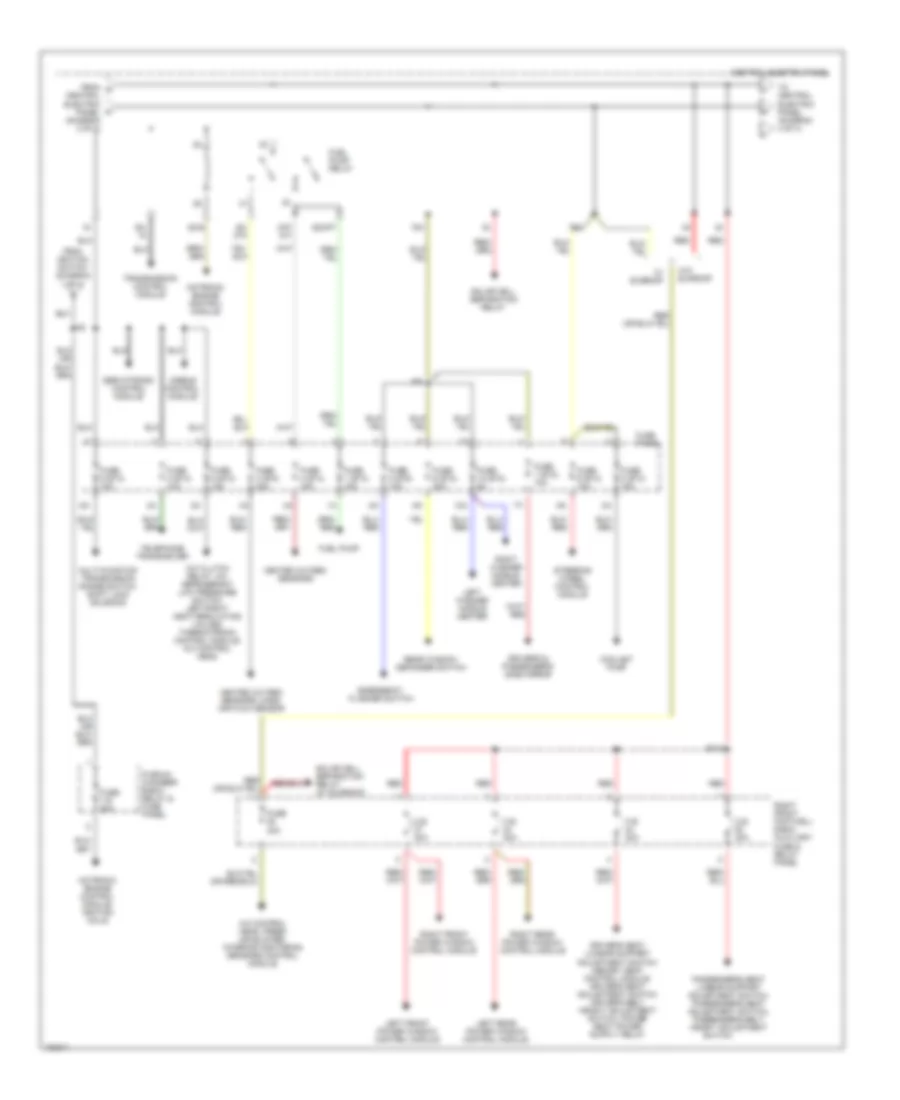
Power Distribution Wiring Diagram (2 of 4) for Audi A8 1997
List of elements for Power Distribution Wiring Diagram (2 of 4) for Audi A8 1997:
- (diagram 1 of 4)
- 75x
- A/c control head, instrument panel interior temperature sensor, instrument cluster, solar cell separation relay, steering wheel control module
- A37
- A51
- Brake light switch, vacuum dump valve
- Central electric panel
- Cigarette lighter
- Coolant pump, left/right heat regulating valve
- Daytime running lights change- over relay
- Daytime running lights switch on relay
- E107
- E108
- E109
- E116
- Emergency flasher switch
- Fog light relay
- Fog light relay, license plate lights (w/o drl), left/right taillights (w/o drl), ashtray light, multi-function transmission range switch, selector lever light relay protection diode, telephone transceiver, a/c control head
- Fog light switch, rear fog light switch
- From a central electric panel b
- From ignition switch (diagram 1 of 4)
- Fuse 1 (st1) 5a
- Fuse 2 (st1) 5a
- Fuse 3 (st1) 15a
- Fuse 3 (st2) 5a
- Fuse 3 (st3) 15a
- Fuse 4 (st1) 15a
- Fuse 4 (st3) 5a
- Fuse 5 (st1) 10a
- Fuse 5 (st2) 15a
- Fuse 6 (st1) 10a
- Fuse 7 (st1) 15a
- Fuse 7 (st3) 15a
- Fuse 9 (st1) 5a
- Fuse 9 (st2) 10a
- Fuse panel
- G43 (above right kick panel)
- Headlight beam adjustment control module
- Headlight dimmer/ flasher switch
- Headlight high beam indicator light
- Instrument cluster
- Instrument cluster, data link connector, solar cell separation relay, selector lever light relay
- Interior lights system
- Lamp control module
- Lamp control module, right parking light, right front side marker light left/right taillights (w/ drl), license plate lights (w/ drl)
- Lamp control module, left parking light, left front side marker light
- Left high beam headlight
- Light light switch switch
- Red
- Right front footwell e-box relay panel
- Right high beam headlight
- Series resistance wiring
- To central electric panel (diagram 3 of 4)
- To central electric panel (diagram 4 of 4)
- W/ drl
- W/o drl
- W/o drl w/ drl
- Wiper/ washer intermittent relay
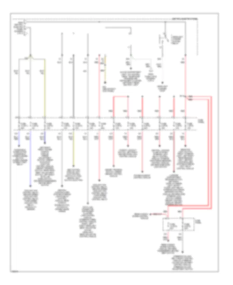
Power Distribution Wiring Diagram (3 of 4) for Audi A8 1997
List of elements for Power Distribution Wiring Diagram (3 of 4) for Audi A8 1997:
- 10a
- 75x
- 87f/ dti
- A/c clutch relay, a/c refrigerant low pressure switch, left/right heat regulating valves, thermotronic control module, a/c control head
- A/c control head, fresh air blower, interior monitoring sensors control module
- A34
- Airbag control module
- B110
- C.b. 30a
- Central electric panel
- Central electric panel (diagram 2 of 4)
- Coolant pump
- Driver's & passenger's side mirror
- Emergency flasher switch
- From g
- From ignition switch (diagram 1 of 4)
- Fuel pump
- Fuel pump relay
- Fuse 1 (st2) 10a
- Fuse 1 (st4) 15a
- Fuse 10 (st2) 5a
- Fuse 2 (st3) 10a
- Fuse 20a
- Fuse 3 (st4) 20a
- Fuse 4 (st4) 15a
- Fuse 40a
- Fuse 5 (st3) 15a
- Fuse 6 (st2) 30a
- Fuse 6 (st3) 10a
- Fuse 8 (st2) 10a
- Fuse 8 (st3) 15a
- Fuse 9 (st3) 10a
- Fuse panel
- Heated oxygen sensors
- Heated oxygen sensors, mass air flow sensor
- Left front power window control module
- Left rear power window control module
- Left washer nozzle heater
- Motronic engine control module
- Motronic engine control module, ignition coils
- Multi-function transmission range switch, shift lock solenoid
- Passenger's seat lumbar support adjustment switch, passenger's seat adjustment switch, passenger's belt height adjustment
- Plenum chamber e-box relay & fuse panel
- Rear window defogger switch
- Red
- Right front footwell e-box auxiliary fuse & relay panel
- Right front power window control module
- Right rear power window control module
- Right washer nozzle heater
- S2/87f
- S3/
- S3/ 87a
- S3/s
- Servotronic control module
- Solar cell separation relay
- Solar cell separation relay (w/ sunroof)
- Steering wheel control module
- Switch
- Telephone transceiver
- To central electric panel (diagram 4 of 4)
- Transmission control module
- W/ sunroof
- W/o sunroof
Power Distribution Wiring Diagram (4 of 4) for Audi A8 1997
List of elements for Power Distribution Wiring Diagram (4 of 4) for Audi A8 1997:
- (diagram 3 of 4)
- 10a
- 58a
- 75x
- Abs control module, anti- slip control switch (w/ fwd), brake light switch (quattro)
- B115
- Central electric panel
- Central locking/ alarm system/ interior light delay control module, interior monitoring sensors control module, driver's side door lock switch
- Central locking/alarm system/interior lights delay control module, rear window shade switch, automatic dimmer inside mirror
- Coolant fan control relay, second speed coolant fan control relay, third speed coolant fan control relay
- Coolant fan control relay, second speed coolant fan control relay, third speed coolant fan relay, air quality sensor
- D51
- Data link connector, instrument cluster, lamp control module, steering wheel control module, radio, left/ right headlight beam adjusting motor, headlight beam adjusting control module
- From fuse 3 (st2) (diagram 2 of 4)
- From j central electric panel k
- Fuse 1 (st3) 15a
- Fuse 1 (st5) 10a
- Fuse 10 (st1) 25a
- Fuse 10 (st4) 10a
- Fuse 10 (st5) 20a
- Fuse 2 (st5) 10a
- Fuse 3 (st5) 10a
- Fuse 4 (st2) 5a
- Fuse 4 (st5) 10a
- Fuse 5 (st5) 15a
- Fuse 6 (st5) 20a
- Fuse 60a
- Fuse 7 (st5) 15a
- Fuse 8 (st5) 10a
- Fuse 9 (st5) 20a
- Fuse panel
- G43 (above right kick panel)
- Glove compartment light, a/c control head, telephone transceiver, instrument cluster, left/right rear ashtray light
- Headlight washer pump
- Headlight washer system relay
- Left/right front power window module, mirror adjustment switch, mirror fold-away function control module, memory program switch, rear head- rest adjustment switch, left/right "b" pillar micro switch, driver's/passenger's heated seat switch
- Luggage compartment release switch, left/right make up mirror light, entry/ floor light relay, interior monitoring sensors control module, driver's side interior lock switch, mirror memory control module, memory program switch
- Memory program switch, mirror memory control module
- Power sunroof control module
- Rear fog light switch, front interior light, left/right rear reading light, central locking/alarm system/interior light delay control module
- Rear window shade control module
- Rear window shade control module, driver's/ passenger's heated seat switch
- Red
- S1/
- S5a
- Steering column/ belt height control module, steering column adjustment control module, steering column adjustment switch
- Window lockout switch, left/right heated door lock control module
- Windshield wiper motor, windshield wiper/washer switch, wiper/washer intermittent relay