POWER DISTRIBUTION
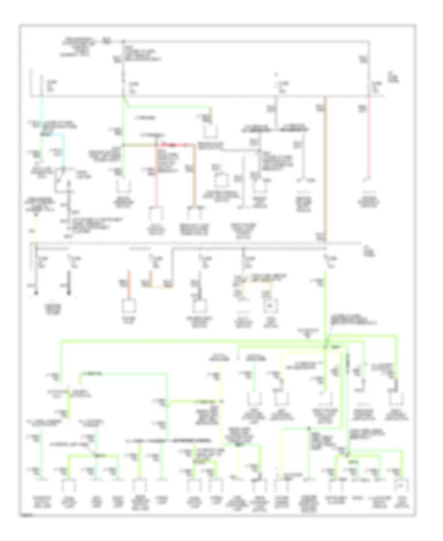
Power Distribution Wiring Diagram (1 of 4) for Ford Econoline E250 1997

List of elements for Power Distribution Wiring Diagram (1 of 4) for Ford Econoline E250 1997:
- (eng control harn, near eng compt fuse box breakout) s116
- (pcm) power relay
- 4 wheel anti-lock brakes (4wabs) module
- 7.3l diesel
- All except 7.3l diesel w/ 215a generator
- All except diesel
- Ambulance package only
- Auxiliary battery relay
- Auxiliary blower motor relay
- Blower motor relay
- C143
- Daytime running lamps (drl)
- Diesel
- Diesel only
- Engine compartment battery
- Engine compartment fuse box
- Frame battery (diesel only)
- From eng compt fuse fuse box (fuse 16) (diagram 1 0f 4)
- From eng compt fuse fuse box (fuse 17) (diagram 1 0f 4)
- From engine compartment fuse box (diagram 1 of 4)
- Fuel pump relay
- Fuse 10a
- Fuse 15a
- Fuse 20a
- Fuse 30a
- Fuse 40a
- Fuse 50a
- Fuse 5a
- Fuse 60a
- Gasoline
- Generator/ voltage regulator
- Glow plug relay
- Horn relay
- Idm relay
- Main light switch
- Modified vehicle power
- Powertrain control module (pcm)
- Red
- Remote/ keyless entry module
- S109 (eng control harn, near eng compt fuse box breakout)
- S110 (eng control harn, near eng compt fuse box breakout)
- S145 (eng control harn, left rear of engine compartment)
- Starter motor
- Starter motor relay
- To eng compt fuse box (fuse 13) (diagram 1 of 4)
- To eng compt fuse box (fuse 8) (diagram 1 of 4)
- To engine compartment fuse box (fuse 9) (diagram 1 0f 4)
- To i/p fuse panel (fuses 40 & 41) (diagram 2 of 4)
- To splice s225 (diagram 3 of 4)
- To splice s227 (diagram 2 of 4)
- Trailer backup lamp relay
- Trailer battery charge relay
- Trailer running lamp relay
- Trailer/ camper adapter (electronic brake)
- W aux heat or a/c
- W/ 4wabs only
- W/ aux battery
- W/ aux battery jumper
- W/ drl only
- W/ remote/ keyless entry
- W/o aux battery
- Wires end in harness
Power Distribution Wiring Diagram (2 of 4) for Ford Econoline E250 1997
List of elements for Power Distribution Wiring Diagram (2 of 4) for Ford Econoline E250 1997:
- (attached to instrument panel assembly, behind instrument cluster)
- (interior lamp harn)
- (lower i/p harn, near brake on/off (boo) switch breakout)
- (main harn, behind left side of i/p)
- (main harn, near main light switch breakout)
- (rear harn, near high mounted stop/ cargo lamp) s405
- (w/o door trim)
- Air bag diagnostic monitor
- All chateau wagons
- All except cutaways
- All vans
- All vans, wagons, & cutaways
- Brake on/off (boo) switch
- Brake pressure switch
- C212
- C217
- C224
- C330
- C335
- Cargo lamp
- Cigar lighter
- Cutaways only
- Data link connector (dlc)
- Dome switch/ lamp
- Dome/map switch and lamp
- Driver's seat control switch
- Eng compartment)
- Except cutaways
- Extended wagons
- From engine compartment d fuse box (fuse 8) (diagram 1 of 4)
- From engine compt fuse box (fuse 18) (diagram 1 0f 4)
- Fuse 10a
- Fuse 15a
- Fuse 20a
- Fuse 25a
- Fuse 30a
- G202
- High mounted stop/cargo lamp
- I/p fuse panel
- Illuminated entry module
- Instrument cluster
- Left courtesy lamp switch
- Left visor lamp
- Main light switch
- Master window/ door lock control switch
- Memory lock module
- Modified vehicle power
- Multi- function switch
- Nca
- Near left "b" pillar) s312
- Power mirror switch
- Power plug
- Radio
- Rear anti-lock brake system (rabs) module
- Rear courtesy lamp switch
- Rear dome/map switch and lamp
- Red
- Remote keyless entry module
- Right courtesy lamp switch
- Right power door lock/ window switch
- Right visor lamp
- S129 (engine control harn, left rear of eng compt)
- S207
- S219
- S221
- S237 (lower i/p harn, near rke data link connector breakout)
- S302 (rear harn, near left seat belt retractor)
- S314
- S505 (left front door harn, in left front door)
- Side door courtesy lamp switch
- W/ full headliner
- W/ rabs only
- W/ remote/ keyless entry
- W/o full headliner
- W/o remote/ keyless entry
- Wagons
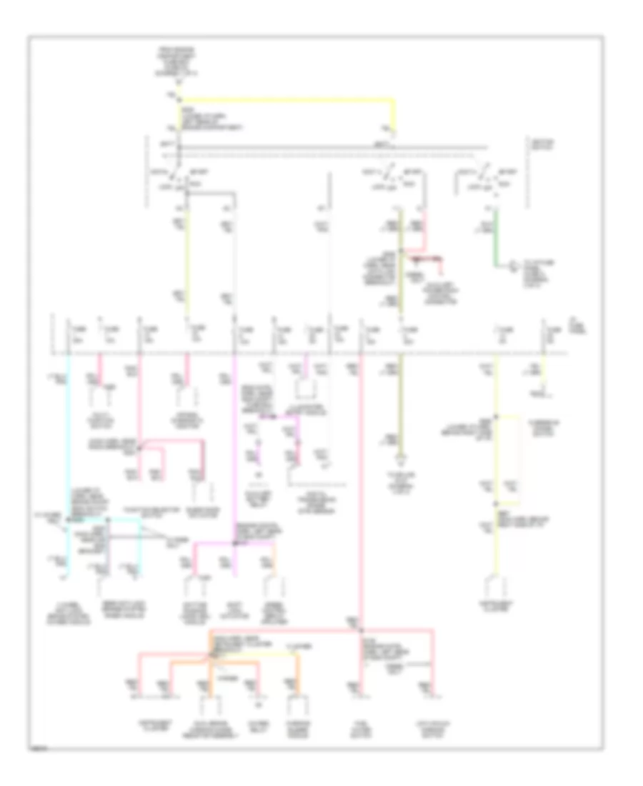
Power Distribution Wiring Diagram (3 of 4) for Ford Econoline E250 1997
List of elements for Power Distribution Wiring Diagram (3 of 4) for Ford Econoline E250 1997:
- (4wabs) relay
- (eng cntrl harn, near eng compt fuse box breakout) s113
- (engine contrl harn, left rear of eng compt) s131
- (lower i/p harn, near brake on/off (boo) switch breakout) s222
- (main harn, near instrument cluster breakout) s213
- (main harn, near radio breakout) s203
- 4 wheel anti-lock brake system (4wabs) module
- Accy
- Air bag diagnostic monitor
- Auxiliary battery relay
- Auxiliary powertrain control connector
- Batt
- Blend door actuator
- C193
- C250
- Daytime running lamps (drl) module
- Diesel only
- Digital transmission range (dtr) sensor
- Dual brake warning diode/ resistor assembly
- From engine compartment fuse box (fuse 23) (diagram 1 of 4)
- Fuel water switch
- Function selector switch
- Fuse 10a
- Fuse 15a
- Fuse 20a
- Fuse 30a
- Fuse 5a
- I/p fuse panel
- Ignition switch
- Illuminated entry module
- Instrument cluster
- Lock
- Low vacuum warning switch
- Multi- function switch
- Nca
- Off
- Overdrive cancel switch
- Rear anti-lock brakes system (rabs) module
- Run
- S146 (engine cntrl harn, left rear of eng compt)
- S200 (main harn, near air bag bracket)
- S229 (lower i/p harn, near data link connector breakout)
- S265 (lower i/p harn, behind right side of i/p)
- Shift lock actuator
- Speed control servo/ apmlifier
- Start
- To i/p fuse panel (fuse 3) (diagram 4 of 4)
- To splice s127 (diagram 4 of 4)
- W 4wabs
- W/ 4wabs only
- W/ rabs only
- W/rabs
- Warning buzzer module
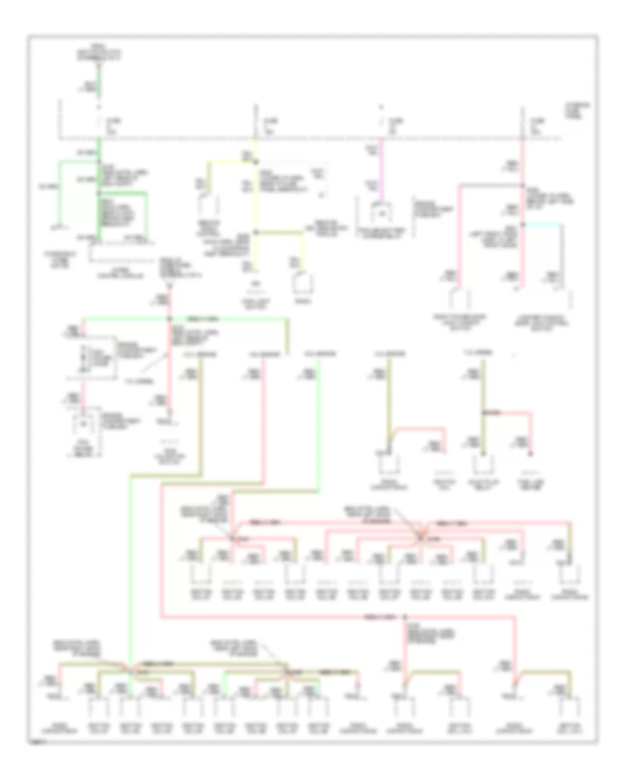
Power Distribution Wiring Diagram (4 of 4) for Ford Econoline E250 1997
List of elements for Power Distribution Wiring Diagram (4 of 4) for Ford Econoline E250 1997:
- (eng cntrl harn, near left bank of engine)
- (eng cntrl harn, near right bank of engine)
- 4.2l engine
- 4.6l engine
- 5.4l engine
- 6.8l engine
- 7.3l diesel
- Eng compt)
- Engine compartment fuse box
- From ignition switch (diagram 3 of 4)
- From i/p fuse panel (fuse 8) (diagram 3 of 4)
- Fuel line heater
- Fuse 15a
- Fuse 30a
- Fuse 5a
- Glow plug relay
- Idle validation switch
- Ign
- Ignition coil
- Ignition coil #1
- Ignition coil #10
- Ignition coil #2
- Ignition coil #3
- Ignition coil #4
- Ignition coil #5
- Ignition coil #6
- Ignition coil #7
- Ignition coil #8
- Ignition coil #9
- Ignition coil 3 & 4
- Interior fuse panel
- Main light switch
- Master window/ door lock control switch
- Nca
- Pcm power diode
- Pcm power relay
- Radio
- Radio capacitor #1
- Radio capacitor #2
- Remote radio control
- Remote/ keyless entry module
- Right power door lock/ window switch
- S1006
- S127 (eng cntrl harn, left rear of eng compt)
- S150 (eng cntrl harn, near right bank of engine)
- S156
- S161
- S208 (main harn, near clock- spring assy breakout)
- S209 (main harn, near clockspring assy breakout)
- S236 (lower i/p harn, behind left side of i/p)
- S245 (lower i/p harn, near i/p fuse panel breakout)
- S501 (left front door harn, in left front door)
- Trailer battery charge relay
- Windshield wiper motor
- Wiper control module