POWER DISTRIBUTION
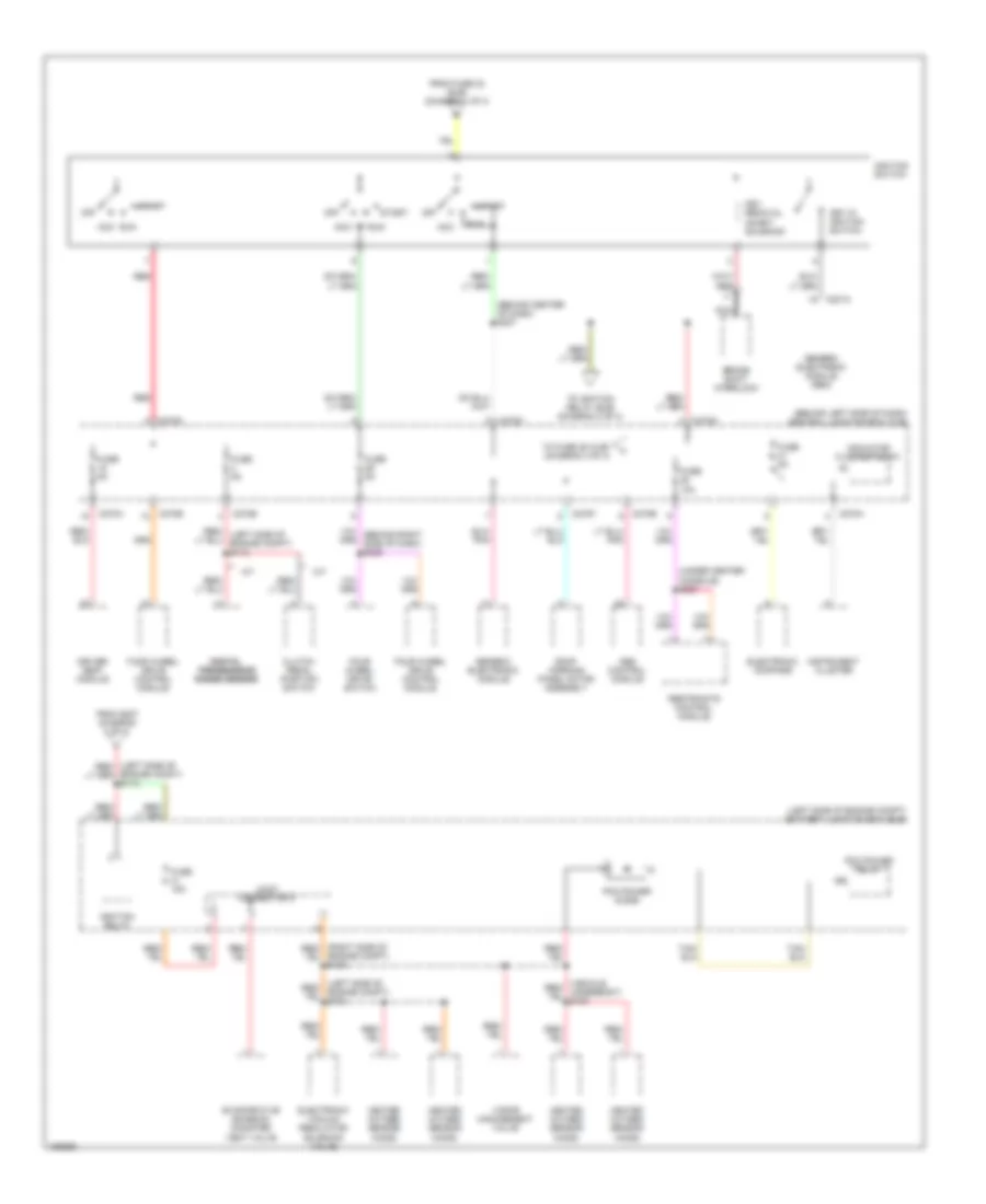
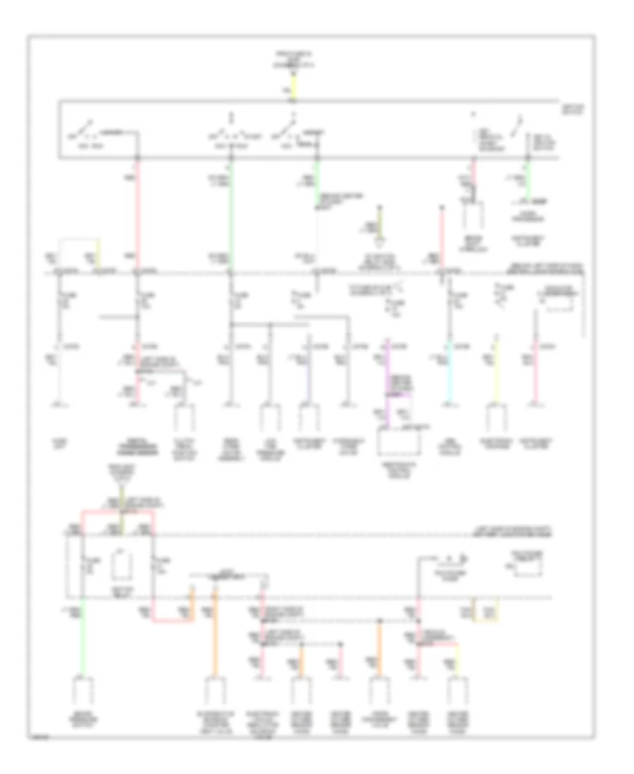
Power Distribution Wiring Diagram, Early Production (1 of 4) for Ford Explorer 2002

List of elements for Power Distribution Wiring Diagram, Early Production (1 of 4) for Ford Explorer 2002:
- (behind center of dash) s218
- (left center of vehicle) s346
- (left side of engine compt) battery junction box (bjb)
- (left side of engine compt) s115
- (right "d" pillar) s412
- (right front of engine compt) s121
- (under center of console) s313
- Abs control module
- Adjustable pedal switch
- Auxiliary a/c relay
- Auxiliary junction block (rear) (on rear "d" pillar)
- Auxiliary junction block (trailer tow) (on rear "d" pillar)
- Battery
- Battery junction box (bjb) (left side of engine compt)
- Blower motor relay
- C102a
- C1030
- C1137
- C135
- C205a
- C239
- C270c
- C281a
- C3008a
- C3009
- C380
- Central junction box (cjb) (behind left side of dash)
- Central security module
- Circuit breaker 30a (left side of engine compt)
- Daytime running lamps module
- Four wheel drive control module
- From fuse 25 (bjb) (diagram 1 of 4)
- From fuse 6 (bjb) (diagram 1 of 4)
- Fuel pump relay
- Fuse 10a
- Fuse 15a
- Fuse 20a
- Fuse 30a
- Fuse 40a
- Fuse 50a
- Fuse 60a
- Fusible link a (12 ga, gray)
- Fusible link b (12 ga, gray)
- Fusible link c (18 ga, brown)
- G202 (right kick panel)
- Generator
- Ignition relay
- Left power seat switch
- Main light switch
- Nca
- Pcm power relay
- Power point console
- Rear window defrost relay
- Red
- Right power seat switch
- S216
- Starter motor
- Starter relay
- Tan/ red
- To accessory delay relay (cjb) (diagram 3 of 4)
- To fuse 1 (cjb) (diagram 3 of 4)
- To fuse 11 (bjb) (diagram 1 of 4)
- To fuse 15 (bjb) (diagram 3 of 4)
- To fuse 16 (cjb) (diagram 4 of 4)
- To fuse 26 (bjb) (diagram 1 of 4)
- To fuse 8 (cjb) (diagram 3 of 4)
- To ignition switch (diagram 2 of 4)
- Trailer electronic brake control module
- Trailer tow relay, battery charge
- Trailer tow relay, left
- Trailer tow relay, parking lamp
- Trailer tow relay, reverse lamp
- Trailer tow relay, right
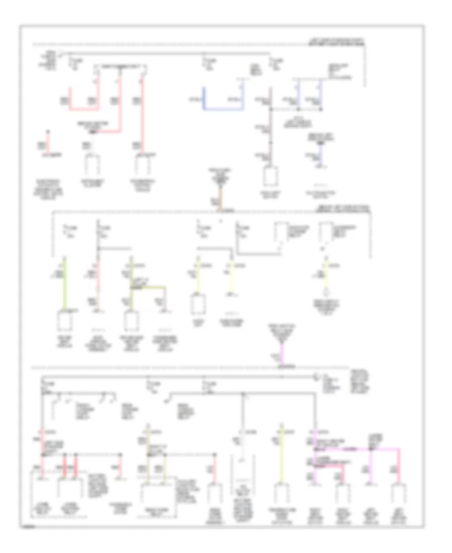
Power Distribution Wiring Diagram, Early Production (2 of 4) for Ford Explorer 2002
List of elements for Power Distribution Wiring Diagram, Early Production (2 of 4) for Ford Explorer 2002:
- (behind center of dash) s207
- (behind left side of dash) central junction box (cjb)
- (left side of engine compt) battery junction box (bjb)
- (under center console) s227
- A/t
- Abs control module
- Acc
- Brake shift interlock
- C201a
- C270a
- C270b
- C270d
- C270e
- C270f
- C270g
- C270h
- Clutch pedal position switch
- Digital digital transmission transmission range sensor range sensor
- Driver seat module
- Electronic compass
- Electronic vacuum regulator solenoid valve
- Engine compt) s113
- Engine compt) s129
- Evaporative emission canister vent valve
- Four wheel drive control module
- Four wheel drive switch
- From fuse 23 (bjb) (diagram 1 of 4)
- From s207 (diagram 2 of 4)
- Fuse 10a
- Fuse 15a
- Fuse 5a
- Generic electronic module
- Generic electronic module (gem)
- Heated oxygen sensor (ho2s)
- Ignition relay
- Ignition switch
- Indicator flasher relay
- Instrument cluster
- Joint connector 2
- Key in ignition switch
- Key removal inhibit solenoid
- M/t
- Nca
- Off
- Pcm power diode
- Pcm power relay
- Red
- Restraints control module
- Roof opening panel motor assembly
- Run
- Start
- To fuse 25 (cjb) (diagram 4 of 4)
- To ignition relay (bjb) (diagram 2 of 4)
- Vapor management valve
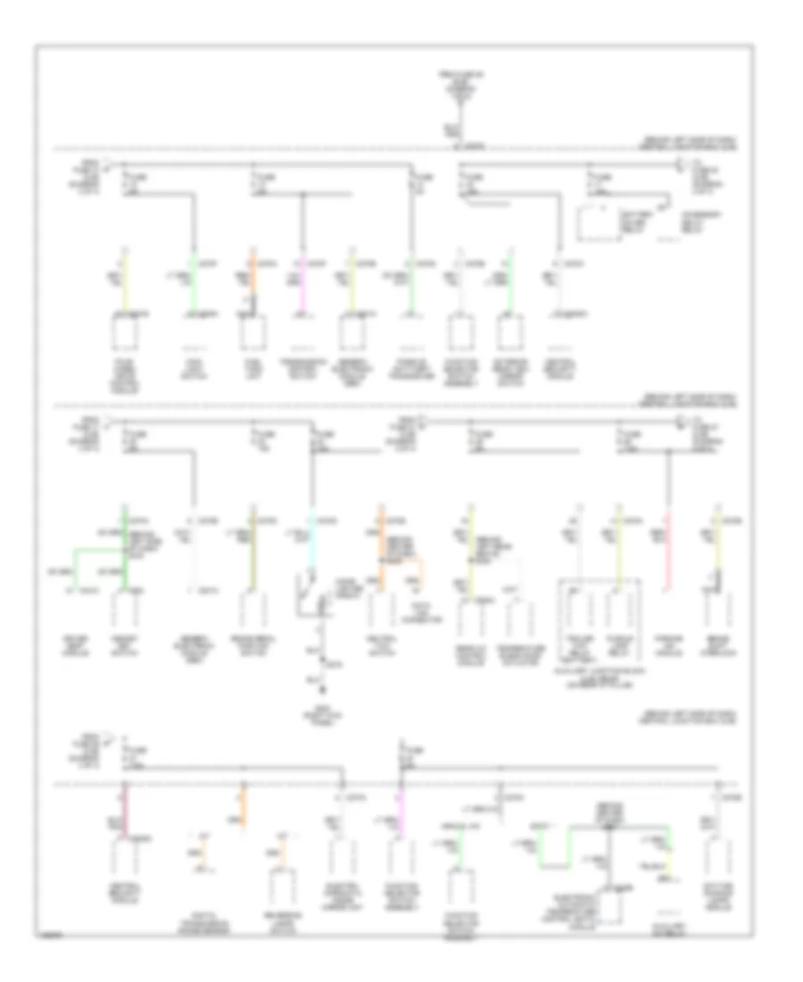
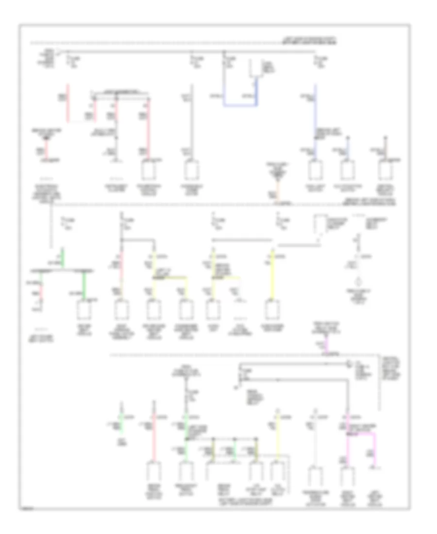
Power Distribution Wiring Diagram, Early Production (3 of 4) for Ford Explorer 2002
List of elements for Power Distribution Wiring Diagram, Early Production (3 of 4) for Ford Explorer 2002:
- (behind center of dash) s232
- (behind left side of dash) central junction box (cjb)
- (behind left side of dash) s205
- (left "a" pillar) s306
- (left side of engine compt) battery junction box (bjb)
- (left side of engine compt) s111
- (right "d" pillar) s411
- (under driver seat) s301
- A/c clutch relay
- Accessory delay relay
- Audio unit
- Auxiliary junction block (ajb) (rear) (on rear "d" pillar)
- Battery junction box (bjb) (left side of engine compt)
- C175a
- C228b
- C270a
- C270b
- C270c
- C270d
- C270f
- C270g
- C341d
- Central junction box (cjb) (behind left side of dash)
- Driver seat module
- Driver side heated seat module
- Electronic automatic temperature control (eatc) module
- From circuit breaker 30a (diagram 1 of 4)
- From fuse 1 (bjb) (diagram 1 of 4) a
- From fuse 23 (bjb) (diagram 1 of 4)
- From ignition relay (bjb) (diagram 1 of 4) e
- Front washer pump relay
- Fuse 10a
- Fuse 15a
- Fuse 20a
- Fuse 30a
- Fuse 5a
- Headlamp relay (w/ autolamps)
- High beam relay
- Indicator flasher relay
- Instrument cluster
- Joint connector 1
- Left heated seat module
- Left seat heater switch
- Main light switch
- Multifunction switch
- Passenger side heated seat module
- Powertrain control module
- Rear washer pump relay
- Rear window defrost relay
- Rear wiper motor assembly
- Rear wiper relay
- Red
- Right heated seat module
- Right seat heater switch
- Roof opening panel motor assembly
- S114 (left side of engine compt)
- Subwoofer amplifier
- Temperature blend door actuator
- To fuse 12 (cjb) (diagram 4 of 4)
- Windshield wiper motor
- Wiper high/low relay
- Wiper run/park relay
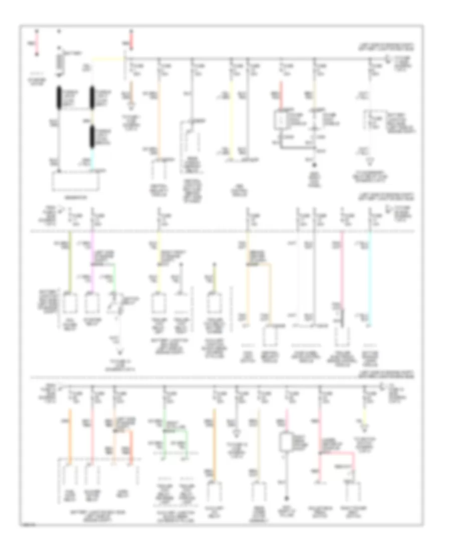
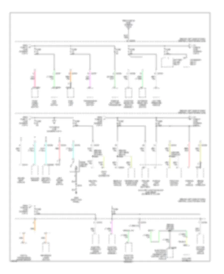
Power Distribution Wiring Diagram, Early Production (4 of 4) for Ford Explorer 2002
List of elements for Power Distribution Wiring Diagram, Early Production (4 of 4) for Ford Explorer 2002:
- (behind center of dash) s245
- (behind center of dash) s247
- (behind left rear seats) s340
- (behind left side of dash) central junction box (cjb)
- A/t
- Accessory delay relay
- Auxiliary a/c relay
- Auxiliary junction block (ajb) (rear) (on rear "d" pillar)
- Battery saver relay
- Brake pedal position switch
- Brake shift interlock
- C201a
- C205a
- C228b
- C270a
- C270b
- C270c
- C270d
- C270e
- C270f
- C270g
- C270h
- C281b
- C3008a
- C3008c
- C341c
- C503
- C938a
- Central security module
- Cigar lighter (front)
- Data link connector
- Daytime running lamps module
- Digital transmission range sensor
- Driver seat module
- Eatc
- Electro- chromatic inside mirror unit
- Electronic automatic temperature control (eatc) module
- Exterior rear view mirror switch
- Four- wheel drive control module
- From fuse 10 (cjb) (diagram 3 of 4)
- From fuse 17 (cjb) (diagram 4 of 4)
- From fuse 21 (cjb) (diagram 2 of 4)
- From fuse 26 (cjb) (diagram 4 of 4)
- From fuse 29 (bjb) (diagram 1 of 4) f
- Fuel tank unit
- Function selector switch assembly
- Fuse 15a
- Fuse 5a
- Fuse 7.5a
- G202 (right kick panel)
- Generic electronic module (gem)
- M/t
- Main light switch
- Manual a/c
- Memory set switch
- Nca
- Neutral tow switch
- Parking aid module
- Passive anti-theft transceiver
- Puddle lamp relay
- Rear a/c control module
- Reversing lamps switch
- S216
- Temperature blend door actuator
- To fuse 20 (cjb) (diagram 4 of 4)
- To fuse 27 (cjb) (diagram 4 of 4)
- Trailer tow relay (battery)
- Transmission control switch
Power Distribution Wiring Diagram, Late Production (1 of 4) for Ford Explorer 2002
List of elements for Power Distribution Wiring Diagram, Late Production (1 of 4) for Ford Explorer 2002:
- (behind center of dash) s259
- (left side of engine compt) battery junction box (bjb)
- (left side of engine compt) s115
- (right front of engine compt) s121
- (under center of console) s313
- Abs control module
- Adjustable pedal switch
- Auxiliary a/c relay
- Auxiliary junction block (rear) (on rear "d" pillar)
- Battery
- Battery junction box (bjb) (left side of engine compt)
- Blower motor relay
- C102a
- C155
- C270c
- C281b
- C3008a
- C3008e
- C3009
- C380
- Central junction box (cjb) (behind left side of dash)
- Central security module
- Daytime running lamps module
- Four wheel drive control module
- From fuse 14 (bjb) (diagram 1 of 4)
- From fuse 6 (bjb) (diagram 1 of 4)
- Fuel pump relay
- Fuse 10a
- Fuse 15a
- Fuse 20a
- Fuse 30a
- Fuse 40a
- Fuse 50a
- Fuse 60a
- Fusible link a (12 ga, gray)
- Fusible link b (12 ga, gray)
- Fusible link c (18 ga, brown)
- G200 (right kick panel)
- G401 (right "d" pillar)
- Generator
- Horn relay
- Ignition relay
- Main light switch
- Nca
- Pcm power relay
- Power point console
- Rear window defrost relay
- Rear wiper motor assembly
- Red
- Right power seat switch
- Right rear power point
- S216
- Starter motor
- Starter relay
- To accessory delay relay (cjb) (diagram 3 of 4)
- To fuse 1 (cjb) (diagram 3 of 4)
- To fuse 10 (cjb) (diagram 3 of 4)
- To fuse 11 (bjb) (diagram 1 of 4)
- To fuse 15 (bjb) (diagram 3 of 4)
- To fuse 16 (cjb) (diagram 4 of 4)
- To fuse 26 (bjb) (diagram 1 of 4)
- To ignition switch (diagram 2 of 4)
- Trailer electronic brake control module
- Trailer tow relay, battery charge
- Trailer tow relay, left
- Trailer tow relay, parking lamp
- Trailer tow relay, reverse lamp
- Trailer tow relay, right
Power Distribution Wiring Diagram, Late Production (2 of 4) for Ford Explorer 2002
List of elements for Power Distribution Wiring Diagram, Late Production (2 of 4) for Ford Explorer 2002:
- (behind center of dash) s207
- (behind center of dash) s261
- (behind left side of dash) central junction box (cjb)
- (left side of engine compt) battery junction box (bjb)
- A/t
- Abs control module
- Acc
- Audio unit
- Brake pressure switch
- Brake shift interlock
- C220b
- C270a
- C270b
- C270d
- C270e
- C270f
- C270g
- C270h
- C310a
- Clutch pedal position switch
- Digital digital transmission transmission range sensor range sensor
- Electronic compass
- Electronic vacuum regulator solenoid valve
- Engine compt) s113
- Engine compt) s129
- Evaporative emission canister vent valve
- From fuse 23 (bjb) (diagram 1 of 4)
- From s207 (diagram 2 of 4)
- Fuse 10a
- Fuse 15a
- Fuse 5a
- Heated oxygen sensor (ho2s)
- Ignition relay
- Ignition switch
- Indicator flasher relay
- Instrument cluster
- Joint connector 2
- Key in ignition switch
- Key removal inhibit solenoid
- Low tire pressure module
- M/t
- Micro- processor
- Nca
- Off
- Pcm power diode
- Pcm power relay
- Rear wiper motor assembly
- Red
- Restraints control module
- Run
- Start
- To fuse 25 (cjb) (diagram 4 of 4)
- To ignition relay (bjb) (diagram 2 of 4)
- Vapor management valve
- Windshield wiper motor
Power Distribution Wiring Diagram, Late Production (3 of 4) for Ford Explorer 2002
List of elements for Power Distribution Wiring Diagram, Late Production (3 of 4) for Ford Explorer 2002:
- (behind center of dash) s232
- (behind left side of dash) central junction box (cjb)
- (behind left side of dash) s205
- (left "a" pillar) s306
- (left side of engine compt) battery junction box (bjb)
- (left side of engine compt) s171
- A/c clutch relay
- Accessory delay relay
- Audio unit
- Battery junction box (bjb) (left side of engine compt)
- Brake pedal position switch
- Brake pedal relay
- C175a
- C228b
- C270a
- C270b
- C270c
- C270d
- C270f
- C270g
- C270h
- C3008e
- C341e
- Central junction box (cjb) (behind left side of dash)
- Central security module
- Driver seat module
- Driver side heated seat module
- Dvd player (if equipped)
- Electronic automatic temperature control (eatc) module
- From fuse 1 (bjb) (diagram 1 of 4) a
- From fuse 23 (bjb) (diagram 1 of 4)
- From fuse 24 (cjb) (diagram 4 of 4) n
- From fuse 47 (bjb) (diagram 1 of 4)
- From ignition relay (bjb) (diagram 1 of 4) e
- Fuse 10a
- Fuse 15a
- Fuse 20a
- Fuse 30a
- Fuse 40a
- High beam relay
- Indicator flasher relay
- Instrument cluster
- Ivd stop lamp relay
- Joint connector 1
- Left heated seat module
- Left power seat switch
- Main light switch
- Multifunction switch
- Nca
- Not used
- Passenger side heated seat module
- Powertrain control module
- Rear window defrost relay
- Red
- Redundant pedal switch
- Right heated seat module
- Roof opening panel motor assembly
- Subwoofer amplifier
- Temperature blend door actuator
- To fuse 12 (cjb) (diagram 4 of 4)
- W/ memory
- W/o memory
- Windshield wiper motor
Power Distribution Wiring Diagram, Late Production (4 of 4) for Ford Explorer 2002
List of elements for Power Distribution Wiring Diagram, Late Production (4 of 4) for Ford Explorer 2002:
- (behind center of dash) s247
- (behind center of dash) s263
- (behind left rear seats) s326
- (behind left side of dash) central junction box (cjb)
- (center console) s264
- A/t
- Accessory delay relay
- Auxiliary a/c relay
- Auxiliary junction block (ajb) (rear) (on rear "d" pillar)
- Battery saver relay
- Brake shift interlock
- C205a
- C228b
- C270a
- C270b
- C270c
- C270d
- C270e
- C270f
- C270g
- C270h
- C284
- C3008e
- C341c
- C938a
- Central security module
- Cigar lighter (front)
- Data link connector
- Daytime running lamps module
- Digital transmission range sensor
- Driver seat module
- Eatc
- Electro- chromatic inside mirror unit
- Electronic automatic temperature control (eatc) module
- Exterior rear view mirror switch
- Four- wheel drive switch
- From fuse 10 (cjb) (diagram 3 of 4)
- From fuse 17 (cjb) (diagram 4 of 4)
- From fuse 22 (cjb) (diagram 2 of 4)
- From fuse 26 (cjb) (diagram 4 of 4)
- From fuse 29 (bjb) (diagram 1 of 4) f
- Fuel tank unit
- Function selector switch assembly
- Fuse 15a
- Fuse 5a
- Fuse 7.5a
- G200 (right kick panel)
- Left power seat switch
- Low tire pressure module
- M/t
- Main light switch
- Manual a/c
- Nca
- Neutral tow switch
- Parking aid module
- Passive anti-theft transceiver
- Puddle lamp relay
- Rear a/c control module
- Red
- Reversing lamps switch
- S216
- Sunload sensor
- Temperature blend door actuator
- To fuse 20 (cjb) (diagram 4 of 4)
- To fuse 23 (cjb) (diagram 3 of 4)
- To fuse 27 (cjb) (diagram 4 of 4)
- Traction control switch
- Trailer tow relay (battery)
- Transmission control switch