ANTI-LOCK BRAKES
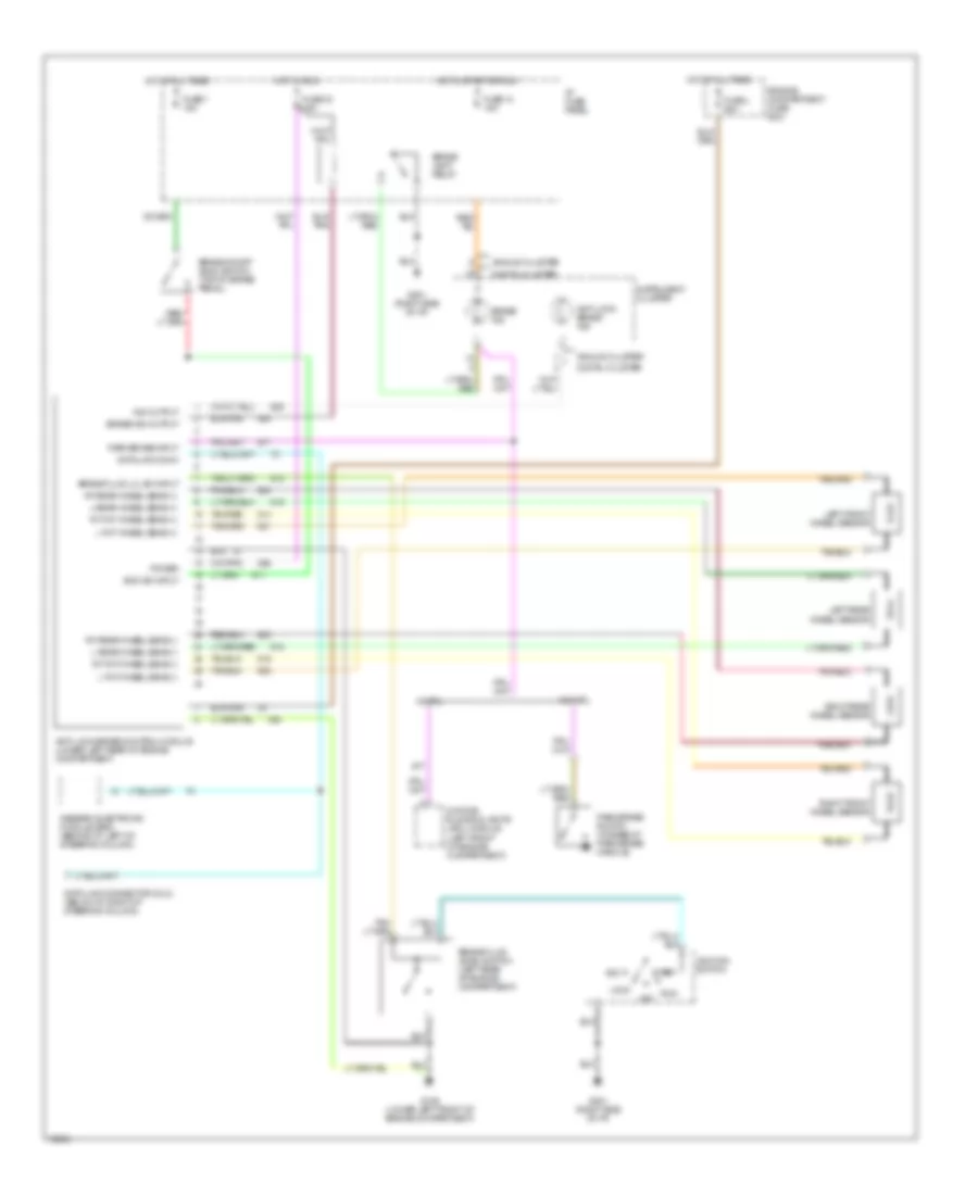
Anti-lock Brake Wiring Diagrams for Ford Windstar GL 1995
List of elements for Anti-lock Brake Wiring Diagrams for Ford Windstar GL 1995:
- Acc
- Analog cluster
- Anti-lock brake control module (lower left rear of engine compartment)
- Anti-lock brake ind
- Boo sw input
- Brake fluid level switch (left rear of engine compartment)
- Brake fluid lvl sw input
- Brake ind
- Brake ind output
- Brake lamp relay
- Brake on/off (boo) switch (top of brake pedal)
- Data link conn
- Data link connector (dlc) (below i/p, right of steering column)
- Daytime running lights (drl) module (left front of engine compartment)
- Digital cluster
- Engine compartment fuse box
- Fuse 14 15a
- Fuse 33 15a
- Fuse 7 15a
- Fuse l 60a
- G106 (lower left front of engine compartment)
- G201 (right side of i/p)
- Generic electronic module (gem) (behind i/p, left of steering column)
- Hot at all times
- Hot in run
- Hot in start or run
- I/p fuse panel
- Ignition switch
- Ind output
- Instrument cluster
- L fnt wheel sens (+)
- L fnt wheel sens (-)
- L rear wheel sens (+)
- L rear wheel sens (-)
- Left front wheel sensor
- Left rear wheel sensor
- Lock
- Off
- Park brake input
- Park brake switch (at base of park brake handle)
- Power
- Right front wheel sensor
- Right rear wheel sensor
- Rt fnt wheel sens (+)
- Rt fnt wheel sens (-)
- Rt rear wheel sens (+)
- Rt rear wheel sens (-)
- Run
- Start
- W/ drl
- W/o drl
 Čeština
 Dansk
Dansk Deutsch
 Ελληνικά
 English
 English
 Español
 Suomi
Suomi Français
 Français
 עברית
עברית Hrvatski
 Magyar
 Italiano
 日本語
日本語 한국어
한국어 Nederlands
 Polski
 Português
 Română
 Русский
 Slovenčina
 Slovenščina
 Svenska
 Türkçe
 中文 (中国)
 Português