SUPPLEMENTAL RESTRAINTS
Supplemental Restraint Wiring Diagram for Mercury Tracer GS 1997
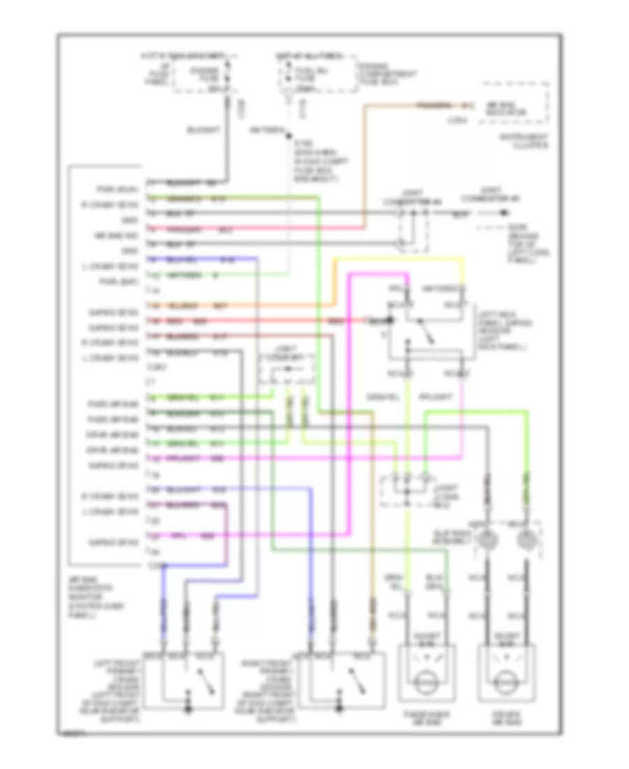
List of elements for Supplemental Restraint Wiring Diagram for Mercury Tracer GS 1997:
- Air bag diagnostic monitor (center dash panel)
- Air bag ind
- Air bag indicator
- C110
- C220
- C254
- C263
- C264
- Driver air bag
- Drvr air bag
- Engine compartment fuse box
- Engine fuse 15a
- Fuel inj fuse 30aa
- G200 (behind top of left cowl panel)
- Gnd
- Hot at all times
- Hot in run or start
- I/p fuse panel
- Instrument cluster
- Joint conn #11
- Joint conn #12
- Joint connector #3
- Joint connector #4
- L crash sens
- Left front primary crash sensor (left front of eng compt, near radiator support)
- Left kick panel safing sensor (left kick panel)
- Nca
- Pass air bag
- Passenger air bag
- Pwr (bat)
- Pwr (run)
- R crash sens
- Red
- Right front primary crash sensor (right front of eng compt, near radiator support)
- S102 (eng harn, in eng compt fuse box breakout)
- Safing sens
- Short bar
- Slip ring assembly
 Čeština
 Dansk
Dansk Deutsch
 Ελληνικά
 English
 English
 Español
 Suomi
Suomi Français
 Français
 עברית
עברית Hrvatski
 Magyar
 Italiano
 日本語
日本語 한국어
한국어 Nederlands
 Polski
 Português
 Română
 Русский
 Slovenčina
 Slovenščina
 Svenska
 Türkçe
 中文 (中国)
 Português