SUPPLEMENTAL RESTRAINTS
Supplemental Restraints Wiring Diagram for Hyundai Tiburon GT 2006
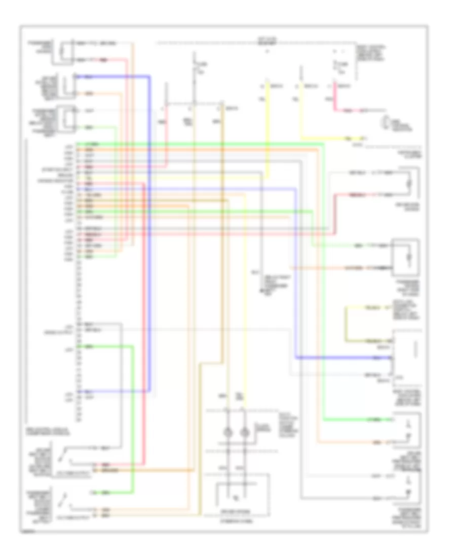
List of elements for Supplemental Restraints Wiring Diagram for Hyundai Tiburon GT 2006:
- (below right front passenger seat) g09
- Air bag indicator
- Atd
- Bcm-ai
- Bcm-im
- Bcm-jm
- Body control module box (behind left side of dash)
- Clock spring
- Crash output
- Data link connector (partial) (below left side of dash)
- Driver air bag
- Driver satellite sensor (below driver seat)
- Driver seat belt buckle switch (on driver seat belt buckle)
- Driver seat belt pretensioner (base of left ``b" pillar)
- Driver side air bag
- Fuse 10a
- Fuse 15a
- Ground
- High
- Hot in on or start
- Instrument cluster
- K-line
- Low
- M10-2
- Multi- function switch (under steering column)
- Nca
- Passenger air bag (right side of dash)
- Passenger satellite sensor (below right front passenger seat)
- Passenger seat belt buckle switch (under passenger seat bottom)
- Passenger seat belt pretensioner (base of right ``b" pillar)
- Passenger side air bag
- Pnk
- Red
- Srs (air bag) indicator
- Srs control module (under rear console)
- Start/on input
- Steering wheel
- Voltage output
 Čeština
 Dansk
Dansk Deutsch
 Ελληνικά
 English
 English
 Español
 Suomi
Suomi Français
 Français
 עברית
עברית Hrvatski
 Magyar
 Italiano
 日本語
日本語 한국어
한국어 Nederlands
 Polski
 Português
 Română
 Русский
 Slovenčina
 Slovenščina
 Svenska
 Türkçe
 中文 (中国)
 Português