ENGINE PERFORMANCE
5.8L
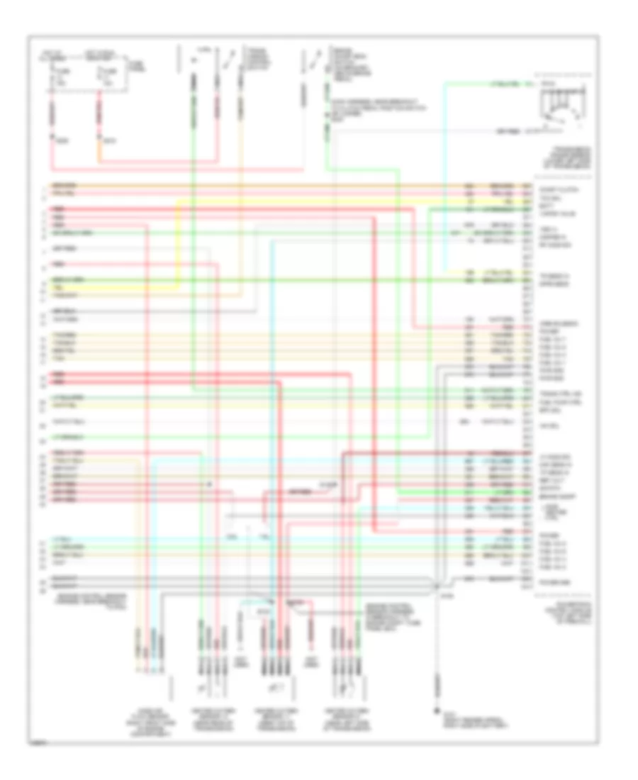
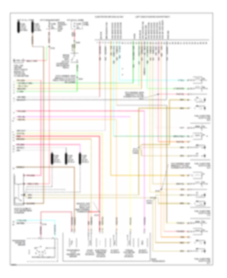
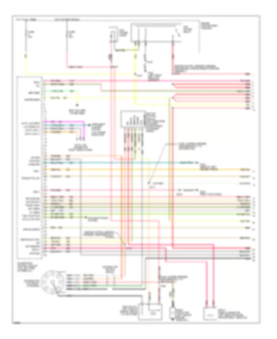
5.8L, Engine Performance Wiring Diagrams, California (1 of 4) for Ford Cab & Chassis F350 1997
 https://portal-diagnostov.com/license.html
Automotive Electricians Portal FZCO
Automotive Electricians Portal FZCO
https://portal-diagnostov.com/license.html
https://portal-diagnostov.com/license.html
Automotive Electricians Portal FZCO
Automotive Electricians Portal FZCO
List of elements for 5.8L, Engine Performance Wiring Diagrams, California (1 of 4) for Ford Cab & Chassis F350 1997:
- (engine control sensor harness, near brake warning resistor/diode assembly) s136
- (engine control sensor harness, near breakout to pcm)
- (fuel charge harness, near breakout to distributor)
- (fuel charge harness, near breakout to ignition coil)
- (low range indicator)
- A/c clutch sig
- Air conditioning system
- Aird solenoid
- Bbp feed
- Body builder power feed
- Case gnd
- Ckp sensor
- Coil
- Data link (+)
- Data link (-)
- Data link connector (right side of dash)
- Data link feps
- Distributor (top front of engine)
- Distributor ignition shield
- Ect sens
- Egr solnd ctrl
- Engine compartment fuse box
- Fuel pump mon
- Fuse 20a
- Fuse 30a
- G104 (rear of left fender apron)
- G108 (left front radiator support)
- G203 (right kick panel)
- Hot at all times
- Hot in start or run
- Iat sens
- Idm
- Idm (fto)
- Ign gnd
- Ignition coil (left side of engine, above valve cover)
- Ignition control module (left rear side of engine compartment, on fender apron)
- Instrument cluster system
- Low rnge 4x4
- Maf sig rtn
- Mil
- Misfire sens
- Nca
- Pcm power diode
- Pcm power relay
- Pip
- Pnk
- Power
- Powertrain control module (top left side of firewall)
- Pwr gnd
- Pwr grd
- Radio capacitor (left side of engine, near coil)
- Red
- Red/
- Rr ho2s sig
- S102
- S104
- S145
- S148
- S171
- S199
- S216
- Spout
- Spout check connector (left rear of engine compartment, near icm)
- Trans ctrl sw
- Trans temp
- Tss 1
- Tss 2
- Vss (-)
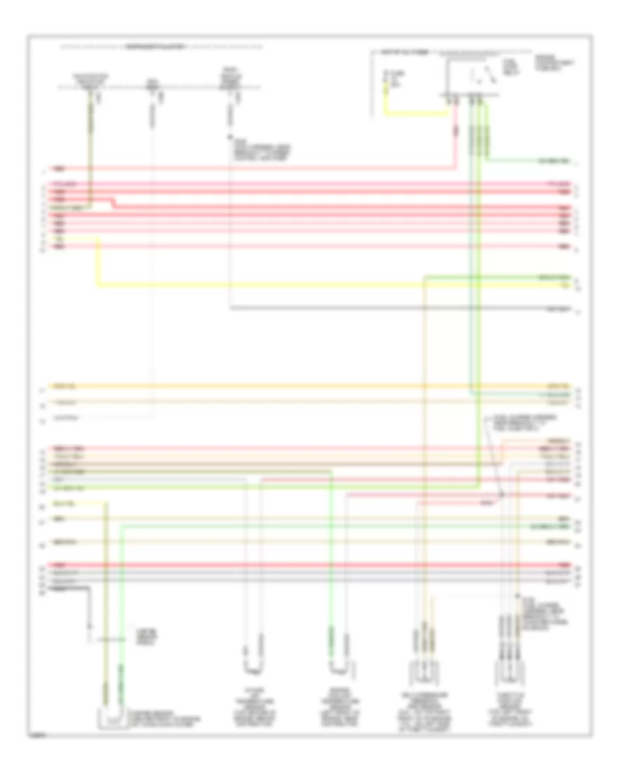
5.8L, Engine Performance Wiring Diagrams, California (2 of 4) for Ford Cab & Chassis F350 1997
List of elements for 5.8L, Engine Performance Wiring Diagrams, California (2 of 4) for Ford Cab & Chassis F350 1997:
- (fuel charge harness, near breakout to fuel injector 3)
- C250
- C251
- C252
- Delta pressure feedback egr sensor (5.8l - on top right front of of engine) (7.5l - on lrft side of throttle body)
- Engine compartment fuse box
- Engine coolant temperature sensor (left front of engine, near distributor)
- Fuel pump relay
- Fuse 20a
- Hot at all times
- Instrument cluster
- Intake air temperature sensor (top center of engine, behind distributor)
- Malfunction indicator input
- Misfire sensor (center front of engine, on timing chain cover)
- Misfire sensor shield
- Nca
- Psom vehicle speed output
- Red
- Rpm input
- S135 (fuel charge harness, near breakout to canister purge solenoid)
- S151
- S246 (main harness, near breakout to speed control amplifier)
- Throttle position sensor (top left front of engine, on throttle body)
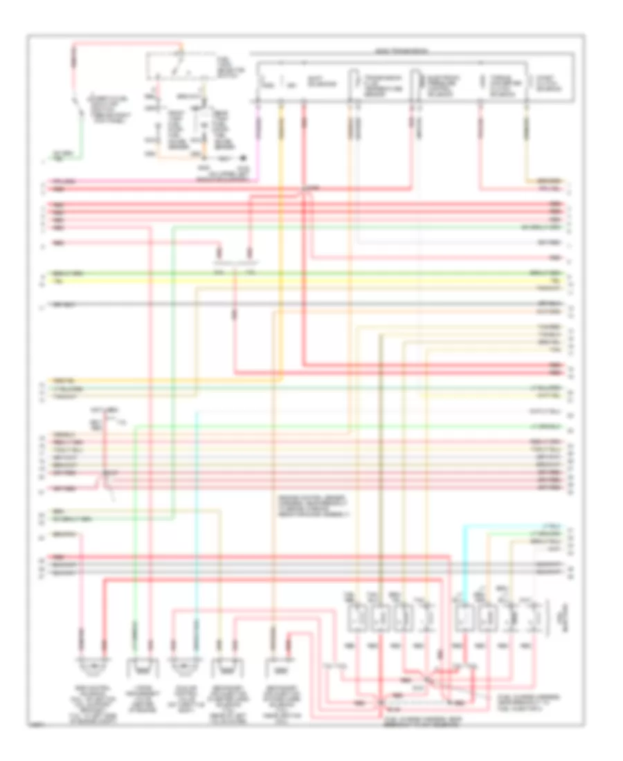
5.8L, Engine Performance Wiring Diagrams, California (3 of 4) for Ford Cab & Chassis F350 1997
List of elements for 5.8L, Engine Performance Wiring Diagrams, California (3 of 4) for Ford Cab & Chassis F350 1997:
- (engine control sensor harness, near breakout to brake warning resistor/diode assembly)
- (fuel charge harness, near breakout to act solenoid)
- (fuel charge harness, near breakout to fuel injector 3)
- (not used)
- 5.8l
- 7.5l
- Coast clutch solenoid
- E4od transmission
- Egr control solenoid (5.8l - on ignition coil support bracket) (7.5l - in left side of engine compt)
- Electronic pressure control solenoid
- Front tank fuel pump/ fuel gauge sender
- Fuel tank selector switch
- G108 (on upper left radiator support)
- Idle air control valve (on throttle body)
- Inertia fuel shut-off switch (behind right kick panel)
- Injectors fuel
- Nca
- Rear tank fuel pump/ fuel gauge sender
- Red
- S137
- S149
- S151
- S169
- S400
- Secondary air injection bypass (airb) solenoid (7.5l) (near ignition coil)
- Secondary air injection diverter (aird) solenoid (7.5l) (rear of left valve cover)
- Shift solenoids
- Ss1
- Ss2
- Tan
- Tan/ red
- Tan/red
- Torque converter clutch solenoid
- Transmission fluid temperature sensor
- Vapor management valve (center of engine)
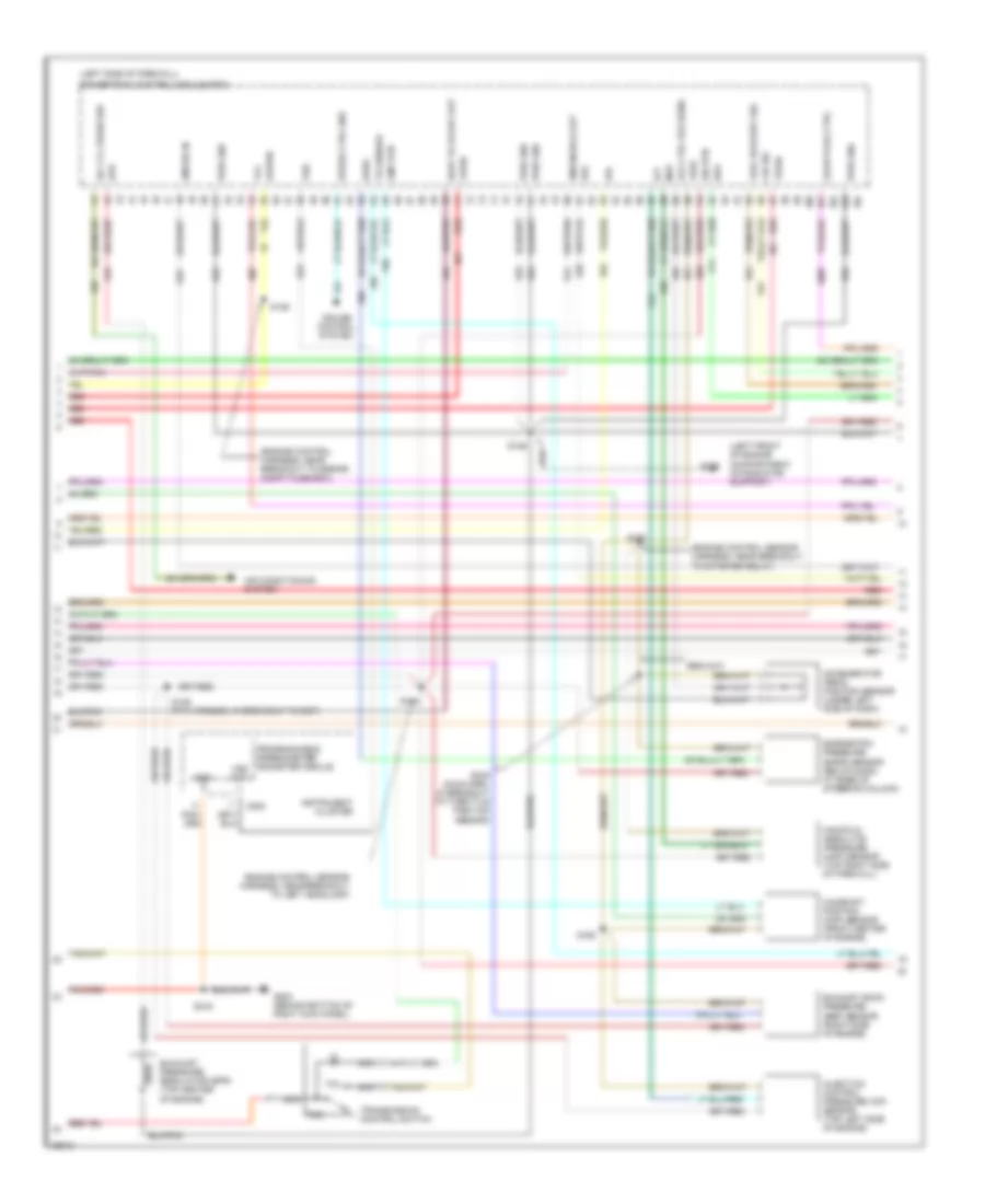
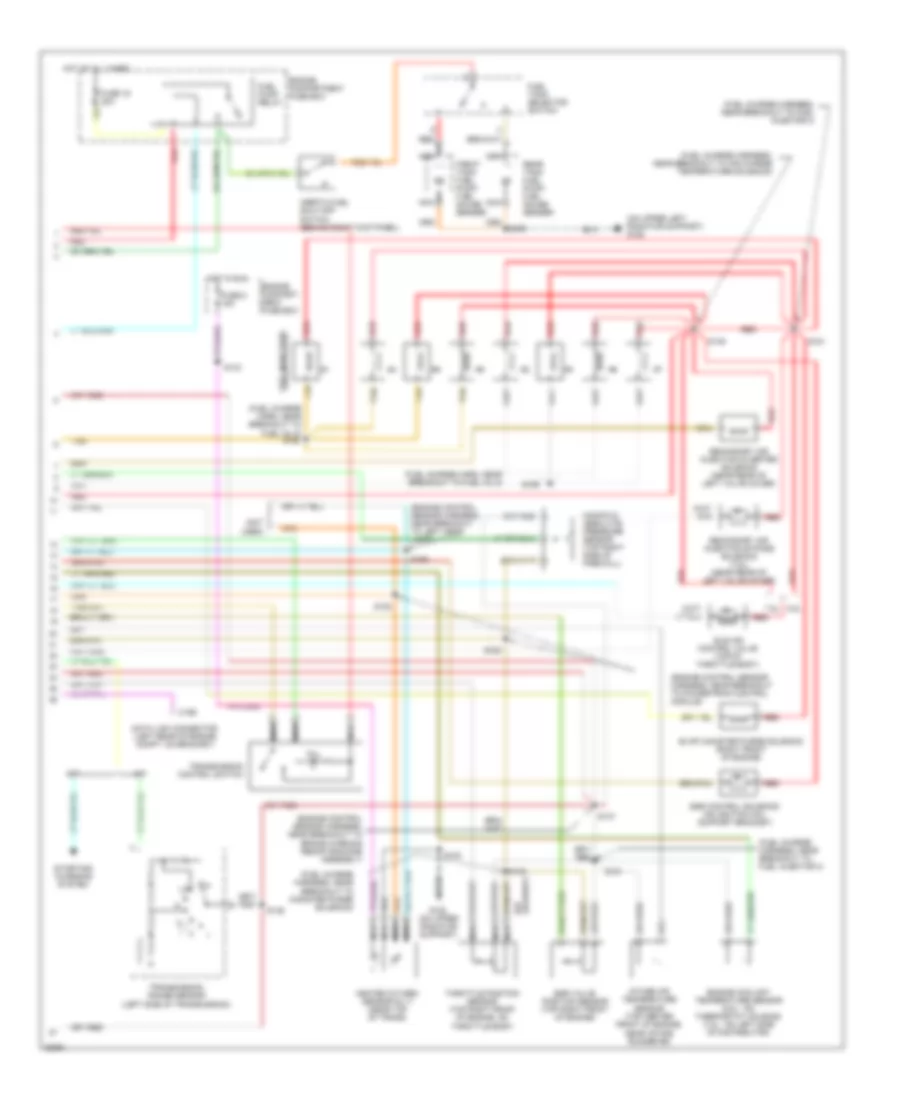
5.8L, Engine Performance Wiring Diagrams, California (4 of 4) for Ford Cab & Chassis F350 1997
List of elements for 5.8L, Engine Performance Wiring Diagrams, California (4 of 4) for Ford Cab & Chassis F350 1997:
- (engine control sensor harness, in breakout to engine compt. fuse panel box)
- (engine control sensor harness, near breakout to pcm)
- (main harness, near breakout to clutch pedal position switch or jumper) s240
- (not used)
- 5.8l
- 7.5l
- Airb solenoid
- Batt
- Brake on/off
- Brake on/off (boo) switch (on bracket, above brake pedal)
- Coast clutch
- Dpfe sens
- Epc sol
- Fuel inj 1
- Fuel inj 2
- Fuel inj 3
- Fuel inj 4
- Fuel inj 5
- Fuel inj 6
- Fuel inj 7
- Fuel inj 8
- Fuel pump ctrl
- Fuse 10a
- Fuse 15a
- Fuse panel
- G101 (right fender apron, right side of battery)
- H02s heater ctrl
- Heated oxygen sensor 11 (near top of transmission)
- Heated oxygen sensor 12 (near rear of transmission)
- Heated oxygen sensor 21 (near left side of transmission)
- Hot at all times
- Hot in run or start
- Iac sol
- Lf ho2s sig
- Maf sens in
- Mass air flow sensor (right front side of engine compartment)
- Misfire in
- Nca
- Power
- Power gnd
- Powertrain control module (top left side of firewall)
- Pwr gnd
- Red
- Ref volt
- Rf ho2s sig
- S106
- S122
- S123
- S146
- S215
- S236
- Sig rtn
- Tan
- Tan/red
- Tcc sol
- Tp sens in
- Tr sens in
- Trans ctrl ind
- Trans- mission control switch
- Transmission range sensor (lower left side of transmission)
- Vapor valve
- Vss (+)
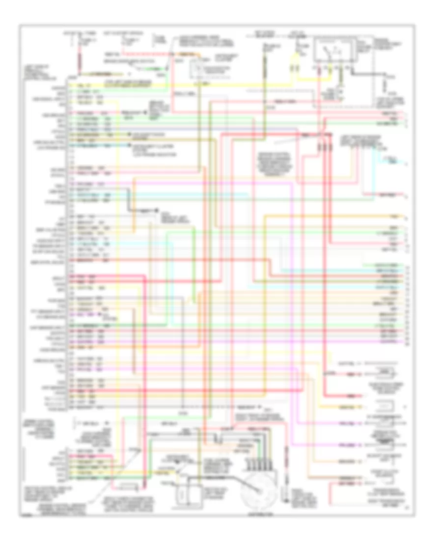
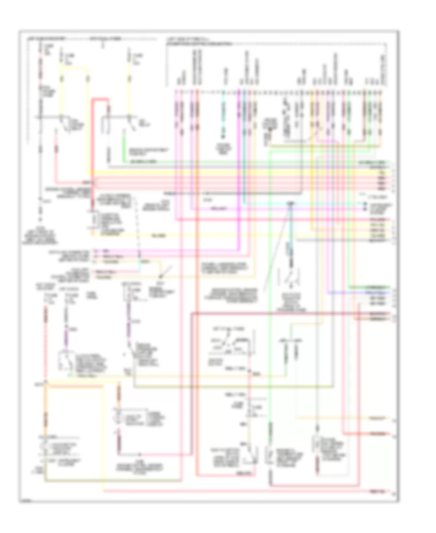
5.8L, Engine Performance Wiring Diagrams, Federal (1 of 2) for Ford Cab & Chassis F350 1997
List of elements for 5.8L, Engine Performance Wiring Diagrams, Federal (1 of 2) for Ford Cab & Chassis F350 1997:
- #1 shift solenoid
- #2 shift solenoid
- (behind bottom of right kick panel) g203
- (engine control sensor harness, near breakout near breakout to pcm)
- (engine control sensor harness, near breakout to brake warning resistor/diode assembly)
- (fuel charge harness, near breakout to distributor)
- (left rear of engine compt, on bracket) data link connector
- (left side of firewall) powertrain control module
- (low range indicator)
- (main harness, near breakout to clutch pedal position switch or jumper)
- (right front of engine compt, on fender apron)
- (top left side of brake/ clutch pedal support)
- (top of upper left radiator support)
- A/c demand sig
- A/c system
- Accs
- Air conditioning system
- Airb solnd ctrl
- Aird solnd ctrl
- Boo
- Brake on/off (boo) switch
- C198
- C250
- C251
- Ccs
- Ckp sensor
- Coast clutch solenoid
- Coil
- Coil wire
- Cse gnd
- Distributor
- E40d transmission
- Ect
- Egr cntrl solnd.
- Egr valve pos
- Electronic pres- sure control solenoid
- Engine compartment fuse box
- Epc
- Evap can solnd.
- Fp enable
- Fpm
- Fuse 13 15a
- Fuse 17 10a
- Fuse 22 20a
- Fuse 30a
- Fuse panel
- G101
- G104 (rear of left fender apron)
- G108
- Gnd
- Ho2s ground
- Ho2s sig input
- Hot at all times
- Hot in run or start
- Hot in start or run
- Iac
- Iat
- Idm
- Idm (fto)
- Ign gnd
- Ignition coil (left rear of engine)
- Ignition control module (left rear of engine compartment, on fender apron)
- Inj 1, 4, 5, 8
- Inj 2, 3, 6, 7
- Instrument cluster
- Instrument cluster system
- Kapwr
- Low range ind
- Malfunction indicator
- Map sensor input
- Nca
- Pcm power diode
- Pcm power relay
- Pip
- Pnk
- Pwr
- Pwr gnd
- Radio capacitor (left side of engine, near ignition coil)
- Red
- S102
- S106
- S136
- S145
- S148
- S169
- S171
- S199
- S215
- S216
- S236
- S240
- S246 (main harness, near breakout to speed control amplifier)
- Sig rtn
- Speed control servo/amplifier assembly (near master cylinder)
- Spout
- Spout check connector (left rear of engine compt, taped to harness, near ignition control module)
- Sto/mil
- Tan
- Tcc
- Tcil
- Tcs
- Tft sensor input
- Torque con- verter clutch solenoid
- Tps input
- Tr sensor input
- Transmission fluid temp sensor
- Tss 1
- Tss 2
- Vip dlc
- Vpwr
- Vref
- Vss ground
- Vss signal input
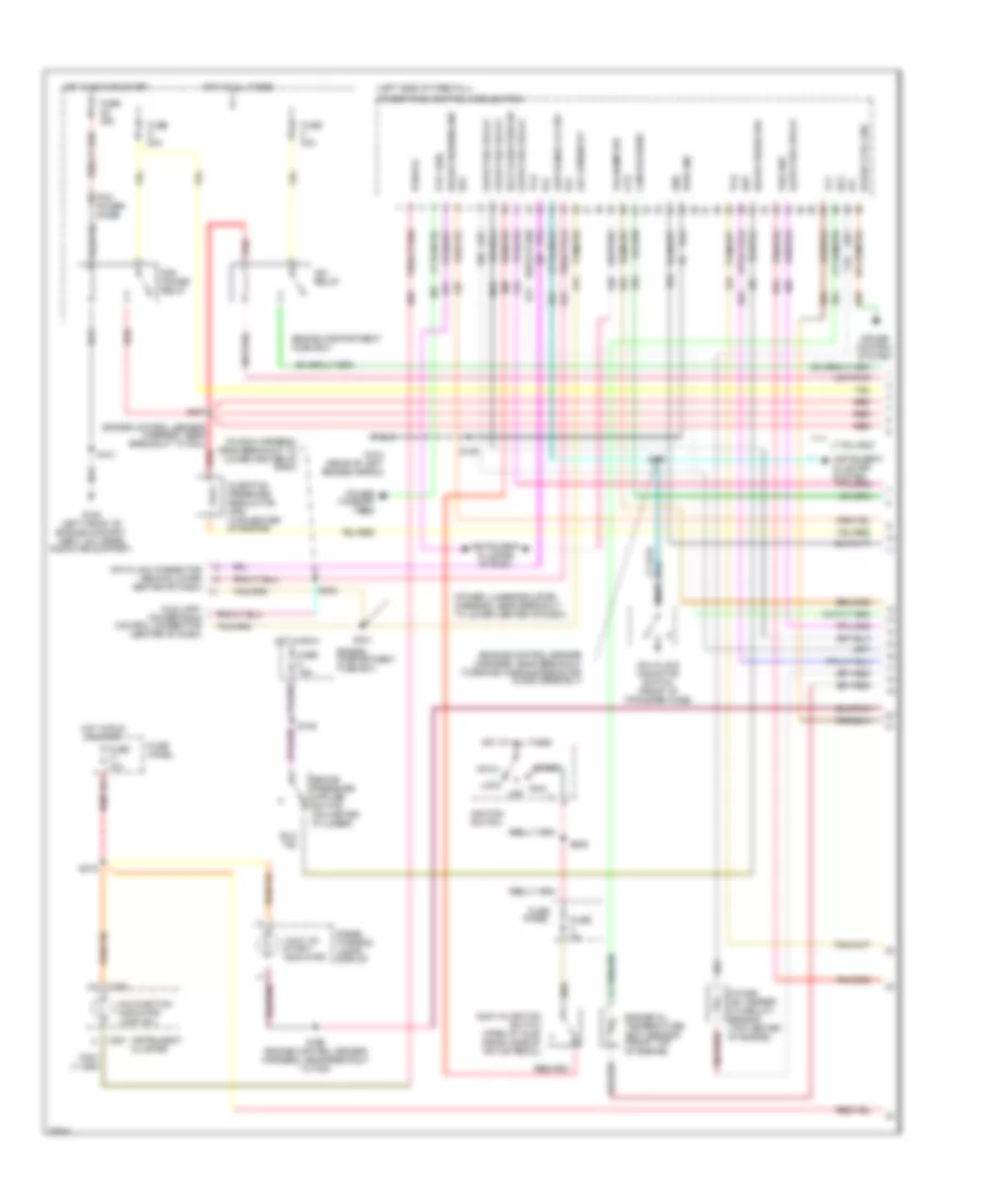
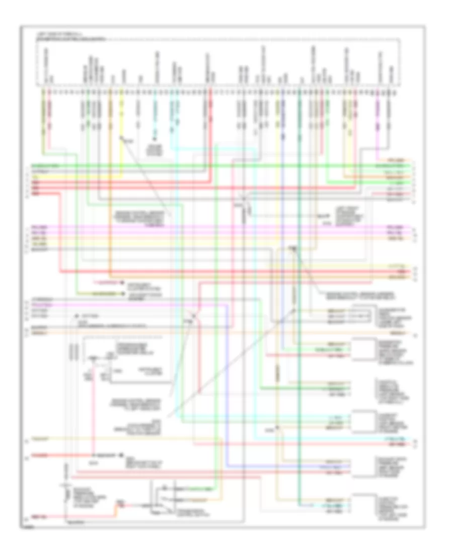
5.8L, Engine Performance Wiring Diagrams, Federal (2 of 2) for Ford Cab & Chassis F350 1997
List of elements for 5.8L, Engine Performance Wiring Diagrams, Federal (2 of 2) for Ford Cab & Chassis F350 1997:
- (engine control sensor harness, near breakout to brake warning resistor/diode assembly)
- (engine control sensor harness, near breakout to left head- lamp)
- (engine control sensor harness, near breakout to powertrain control module)
- (fuel charge harn, near breakout to fuel inj 5)
- (fuel charge harn, near breakout to fuel inj 8)
- (fuel charge harness, near breakout to air charge temperature solenoid)
- (fuel charge harness, near breakout to canister purge solenoid)
- (fuel charge harness, near breakout to fuel injector 3)
- (not used)
- (on upper left radiator support) g108
- (on upper radiator support)
- 5.8l
- 7.5l
- A/t
- C199
- Data link connector (left rear of engine compt, on bracket)
- Egr control solenoid (on ignition coil support bracket)
- Egr valve position sensor (top right front of engine)
- Engine compart- ment fuse box
- Engine compartment fuse box
- Engine coolant temperature sensor (5.8l - on thermostat housing) (7.5l - on left side of distributor)
- Evap canister purge solenoid (right front of engine)
- Front tank fuel pump/ fuel gauge sender
- Fuel injectors
- Fuel pump relay
- Fuel tank selector switch
- Fuse 16 20a
- Fuse 5 15a
- G108
- Heated oxygen sensor no.11 (near top of trans)
- Hot at all times
- Hot in run
- Idle air control valve (top of throttle body)
- Inertia fuel shut-off switch (behind right kick panel)
- Intake air temperature sensor (top center front of engine, near intake runner #6)
- M/t
- Manifold absolute pressure sensor (top right side of firewall)
- Nca
- Rear tank fuel pump/ fuel gauge sender
- Red
- S102
- S122
- S134
- S135
- S137
- S146
- S149
- S151
- S159
- S160
- S163
- S165
- S400
- Secondary air injection bypass solenoid (7.5l) (near rear of left valve cover)
- Secondary air injection diverter solenoid (near rear of left valve cover)
- Starting/ charging system
- Tan
- Tcil
- Throttle position sensor (top right front of engine, on throttle body)
- Transmission control switch
- Transmission range sensor (left side of transmission)
7.3L
7.3L DI Turbo Diesel, Engine Performance Wiring Diagrams, California (1 of 3) for Ford Cab & Chassis F350 1997
List of elements for 7.3L DI Turbo Diesel, Engine Performance Wiring Diagrams, California (1 of 3) for Ford Cab & Chassis F350 1997:
- "wait to start" indicator
- (engine control sensor harness, near breakout to brake warning resistor/ diode assembly)
- (engine control sensor harness, near breakout to pcm)
- (in main harness, near breakout to lower center of dash)
- (left side of firewall)
- (power lumbar/bolster harness, near breakout to lower center of dash)
- 4x4 hi/low indicator switch (front of transfer case)
- Acc
- Aux rpm input
- Auxiliary powertrain control connector (center of dash)
- Brake press sw
- Brake warning ind
- C250
- C251
- Cam pos sens
- Ccs
- Cruise control system
- Data link connector (behind lower center of dash)
- Diesel warning lamps display
- Dlc
- Ebp
- Engine compartment fuse box
- Engine oil temperature (eot) sensor (front top of engine)
- Eot
- Fuse 10a
- Fuse 15a
- Fuse 20a
- Fuse 30a
- Fuse 3a
- Fuse panel
- G104 (rear of left fender apron)
- G108 (left front of engine compart- ment, on upper radiator support)
- Glow plug relay
- Gnd
- Hot at all times
- Hot in run
- Hot in run or start
- Iat
- Idle validation sw
- Idle validation switch (open at idle) (near accele- rator pedal)
- Idm relay
- Ignition switch
- Injection pressure regulator (ipr) (top center of engine)
- Instrument cluster
- Instrument cluster system
- Intake air temper- ature (iat) sensor (top center of engine)
- Lock
- Low range 4x4 sw
- Malfunction indicator lamp (mil)
- Nca
- Off
- Pcm dlc
- Pcm power diode
- Pcm power relay
- Power take-off feed
- Powertrain control module (pcm)
- Pto feed
- Pwr gnd
- Red
- Run
- S101
- S105
- S125
- S157
- S166 (engine control sensor harness, near breakout to pcm)
- S174
- S206
- S215
- S241
- S243
- Speed ctrl gnd
- Ss1
- Start
- Tachometer
- Tcil
- Tcs
- Tft
- Vss gnd
7.3L DI Turbo Diesel, Engine Performance Wiring Diagrams, California (2 of 3) for Ford Cab & Chassis F350 1997
List of elements for 7.3L DI Turbo Diesel, Engine Performance Wiring Diagrams, California (2 of 3) for Ford Cab & Chassis F350 1997:
- (engine control harness, near breakout to engine compt fuse box)
- (engine control sensor harness, near breakout to left headlamp)
- (engine control sensor harness, near breakout to starter relay)
- (left front of engine compartment, on radiator support)
- (left side of firewall)
- A/c cyl press sw
- Accelerator pedal position sensor (under left side of dash)
- Accl pdl pos sens
- Air conditioning system
- Baro
- Barometric pressure (baro) sensor (below dash, at base of steering column)
- Boo
- C252
- Camshaft position (cmp) sensor (front center of engine)
- Cid sig
- Cmp rtn
- Cruise control system
- Epc
- Epr
- Exhaust back pressure (ebp) sensor (right side of engine)
- Exhaust pressure regulator (epr) (top center of engine)
- Fuel delivery sig
- G108
- G203 (behind bottom of right kick panel)
- Glow plug ctrl
- Gnd
- Icp
- Idm enable out
- Idm sig in
- Injection control pressure (icp) sensor (top left side of engine)
- Instrument cluster
- Ipr
- Kapwr
- Manifold absolute pressure (map) sensor (top right side of firewall)
- Map
- Nca
- Powertrain control module (pcm)
- Programmable speedometer/ odometer module
- Pwr gnd
- Red
- S106
- S126
- S129 (pia harness, in breakout to ect)
- S163
- S164
- S192
- S216
- S235 (main harn, in breakout to throttle position sensor)
- Sig rtn
- Speed ctrl gnd
- Tcc
- Tcil
- Tcs
- Tr sensor
- Transmission control switch
- Vpwr
- Vref
- Vss
- Vss out
- Wait to start out
7.3L DI Turbo Diesel, Engine Performance Wiring Diagrams, California (3 of 3) for Ford Cab & Chassis F350 1997
List of elements for 7.3L DI Turbo Diesel, Engine Performance Wiring Diagrams, California (3 of 3) for Ford Cab & Chassis F350 1997:
- #1 shift solenoid
- #2 shift solenoid
- (backup lamp switch to rear lamp feed harness, in breakout)
- (in pia harn)
- (left side of engine compartment)
- (main harness, near breakout to clutch pedal position switch or jumper)
- (pia harness, near breakout to fuel charge pump motor)
- (pia harness, near breakout to fuel charge pump motor) s141
- Brake on/off (boo) switch (on bracket, above brake pedal)
- Cid sig in
- Coast clutch solenoid
- E4od transmission
- Electronic pressure control solenoid
- Engine compart- ment fuse box
- Fuel delivery sig
- Fuel inj feed left
- Fuel inj feed right
- Fuel injector #1
- Fuel injector #2
- Fuel injector #3
- Fuel injector #4
- Fuel injector #5
- Fuel injector #6
- Fuel injector #7
- Fuel injector #8
- Fuel injectors/ glow plugs (1,3)
- Fuel injectors/ glow plugs (2,4)
- Fuel injectors/ glow plugs (5,7)
- Fuel injectors/ glow plugs (6,8)
- Fuel line heater (right side of engine, on top of fuel filter/heater)
- Fuse 15a
- Fuse 30a
- Fuse panel
- Glow plug relay (top center rear of engine)
- Hot at all times
- Hot in run or start
- Idm feedback sig
- Inj shield gnd
- Injector driver module (idm)
- Nca
- Pwr gnd
- Red
- S112
- S113
- S128
- S142
- S143
- S146
- S236
- S240
- Sig rtn
- Tan
- Tan/red
- Torque converter clutch solenoid
- Transmission fluid temperature sensor
- Transmission range (tr) sensor
- Vpwr
7.3L DI Turbo Diesel, Engine Performance Wiring Diagrams, Federal (1 of 3) for Ford Cab & Chassis F350 1997
List of elements for 7.3L DI Turbo Diesel, Engine Performance Wiring Diagrams, Federal (1 of 3) for Ford Cab & Chassis F350 1997:
- "wait to start" indicator
- (a/t)
- (engine control sensor harness, near breakout to brake warning resistor/ diode assembly)
- (engine control sensor harness, near breakout to pcm)
- (in main harness, near breakout to lower center of dash)
- (left side of firewall)
- (m/t)
- (power lumbar/bolster harness, near breakout to center of dash)
- 4x4 hi/low indicator switch (front of transfer case)
- A/t
- Acc
- Aux rpm input
- Auxiliary powertrain control connector (center of dash)
- Brake press sw
- Brake warning ind
- C250
- C251
- Clutch pedal position switch (top right side of brake/clutch pedal support)
- Cruise control system
- Data link connector (behind lower center of dash)
- Diesel warning lamps display
- Dlc
- Ebp
- Engine compartment fuse box
- Engine oil temperature (eot) sensor (front top of engine)
- Eot
- Fuse 10a
- Fuse 15a
- Fuse 20a
- Fuse 30a
- Fuse 3a
- Fuse panel
- G104 (rear of left fender apron)
- G108 (left front of engine compart- ment, on upper radiator support)
- Gnd
- Hot at all times
- Hot in run
- Hot in run or start
- Iat
- Idle validation sw
- Idle validation switch (open at idle) (near accele- rator pedal)
- Idm relay
- Ignition switch
- Injection pressure regulator (ipr) (top center of engine)
- Instrument cluster
- Instrument cluster system
- Intake air temper- ature (iat) sensor (top center of engine)
- Lock
- Low range 4x4 sw
- M/t
- Malfunction indicator lamp (mil)
- Map
- Nca
- Off
- Pcm dlc
- Pcm power diode
- Pcm power relay
- Power take-off feed
- Powertrain control module (pcm)
- Pto feed
- Pwr gnd
- Red
- Run
- S101
- S105
- S125
- S157
- S166 (engine control sensor harness, near breakout to pcm)
- S174
- S206
- S215
- S241
- S242
- S243
- Speed ctrl gnd
- Ss1
- Ss2
- Start
- Tcc
- Tcs or cpp
- Tft
- Vss gnd
7.3L DI Turbo Diesel, Engine Performance Wiring Diagrams, Federal (2 of 3) for Ford Cab & Chassis F350 1997
List of elements for 7.3L DI Turbo Diesel, Engine Performance Wiring Diagrams, Federal (2 of 3) for Ford Cab & Chassis F350 1997:
-
-
- (engine control sensor harness, near breakout to engine compartment fuse box)
- (engine control sensor harness, near breakout to left headlamp)
- (engine control sensor harness, near breakout to starter relay)
- (left front of engine compartment, on radiator support)
- (left side of firewall)
- A/c cyl press sw
- Accelerator pedal position sensor (under left side of dash)
- Accl pdl pos sens
- Air conditioning system
- Baro
- Barometric pressure (baro) sensor (below dash, at base of steering column)
- Boo
- C252
- Cam pos sens
- Camshaft position (cmp) sensor (front center of engine)
- Ccs
- Cid sig
- Cmp rtn
- Cruise control system
- Epc
- Epr
- Exhaust back pressure (ebp) sensor (right side of engine)
- Exhaust pressure regulator (epr) (top center of engine)
- Fuel delivery sig
- G108
- G203 (behind bottom of right kick panel)
- Glow plug ctrl
- Gnd
- Icp
- Idm enable out
- Idm sig in
- Injection control pressure (icp) sensor (top left side of engine)
- Instrument cluster
- Instrument cluster system
- Ipr
- Kapwr
- Manifold absolute pressure (map) sensor (top right side of firewall)
- Nca
- Powertrain control module (pcm)
- Programmable speedometer/ odometer module
- Pwr gnd
- Red
- S106
- S126
- S129 (pia harness, in breakout to ect)
- S163
- S164
- S192
- S216
- S235 (main harness, in breakout to throttle position sensor)
- Sig rtn
- Speed ctrl gnd
- Tachometer
- Tcil
- Tcs
- Tr sensor
- Transmission control switch
- Vpwr
- Vref
- Vss
- Vss out
- Wait to start out
7.3L DI Turbo Diesel, Engine Performance Wiring Diagrams, Federal (3 of 3) for Ford Cab & Chassis F350 1997
List of elements for 7.3L DI Turbo Diesel, Engine Performance Wiring Diagrams, Federal (3 of 3) for Ford Cab & Chassis F350 1997:
- #1 shift solenoid
- #2 shift solenoid
- (backup lamp switch to rear lamp feed harness, in breakout to transmission)
- (left side of engine compartment)
- (main harness, near breakout to clutch pedal position switch or jumper)
- (pia harness, near breakout to fuel charge pump motor)
- (pia harness, near breakout to fuel charge pump motor) s141
- Brake on/off (boo) switch (brake/clutch pedal support)
- Cid sig in
- Coast clutch solenoid
- E4od transmission
- Electronic pressure control solenoid
- Engine compart- ment fuse box
- Fuel delivery sig
- Fuel inj feed left
- Fuel inj feed right
- Fuel injector #1
- Fuel injector #2
- Fuel injector #3
- Fuel injector #4
- Fuel injector #5
- Fuel injector #6
- Fuel injector #7
- Fuel injector #8
- Fuel injectors/ glow plugs (1,3)
- Fuel injectors/ glow plugs (2,4)
- Fuel injectors/ glow plugs (5,7)
- Fuel injectors/ glow plugs (6,8)
- Fuel line heater (right side of engine, on top of fuel filter/heater)
- Fuse 15a
- Fuse 30a
- Fuse panel
- Glow plug relay (top center rear of engine)
- Hot at all times
- Hot in run or start
- Idm feedback sig
- Inj shield gnd
- Injector driver module (idm)
- Nca
- Pwr gnd
- Red
- S112 (in pia harn)
- S113 (in pia harn)
- S128
- S142
- S143
- S146
- S236
- S240
- Sig rtn
- Tan
- Tan/red
- Torque converter clutch solenoid
- Transmission fluid temperature sensor
- Transmission range (tr) sensor
- Vpwr
7.5L
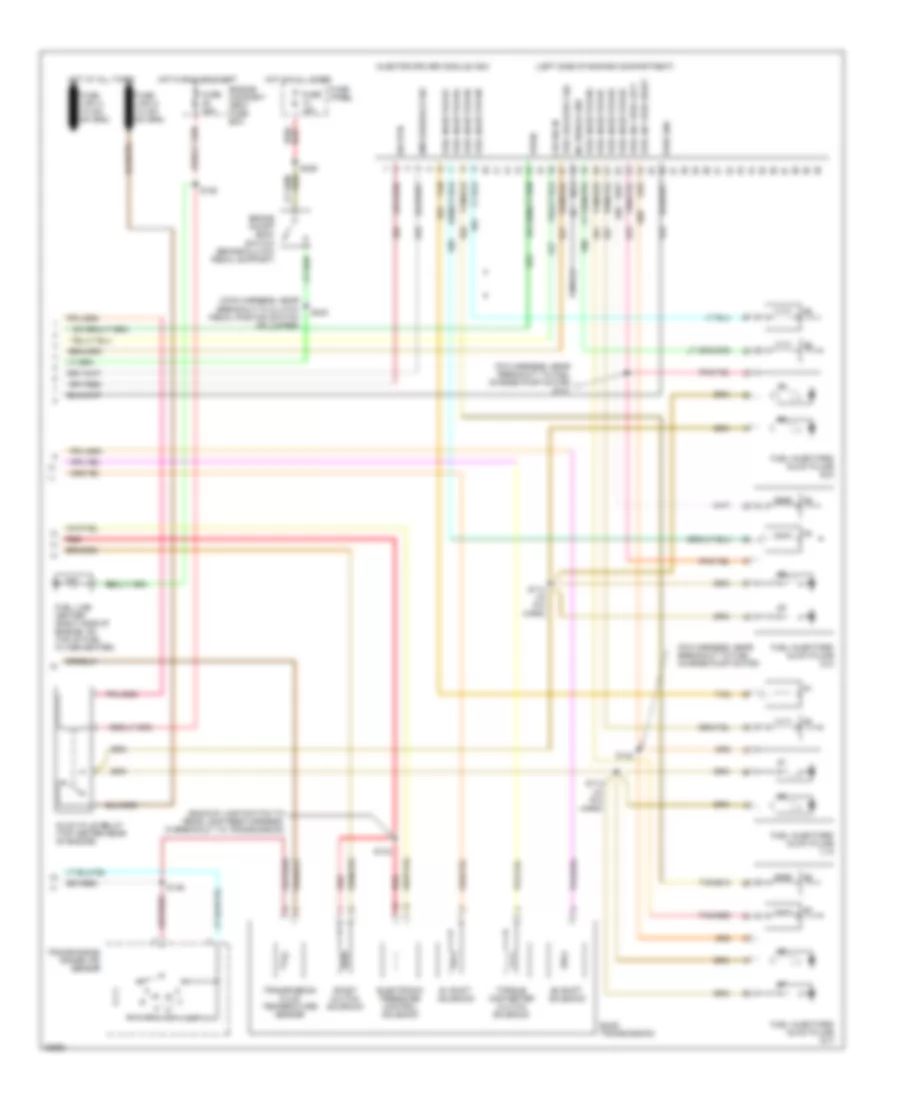
7.5L, Engine Performance Wiring Diagrams, California (1 of 4) for Ford Cab & Chassis F350 1997
List of elements for 7.5L, Engine Performance Wiring Diagrams, California (1 of 4) for Ford Cab & Chassis F350 1997:
- (engine control sensor harness, near brake warning resistor/diode assembly) s136
- (engine control sensor harness, near breakout to pcm)
- (fuel charge harness, near breakout to distributor)
- (fuel charge harness, near breakout to ignition coil)
- (low range indicator)
- A/c clutch sig
- Air conditioning system
- Aird solenoid
- Bbp feed
- Body builder power feed
- Case gnd
- Ckp sensor
- Coil
- Data link (+)
- Data link (-)
- Data link connector (right side of dash)
- Data link feps
- Distributor (top front of engine)
- Distributor ignition shield
- Ect sens
- Egr solnd ctrl
- Engine compartment fuse box
- Fuel pump mon
- Fuse 20a
- Fuse 30a
- G104 (rear of left fender apron)
- G108 (left front radiator support)
- G203 (right kick panel)
- Hot at all times
- Hot in start or run
- Iat sens
- Idm
- Idm (fto)
- Ign gnd
- Ignition coil (left side of engine, above valve cover)
- Ignition control module (left rear side of engine compartment, on fender apron)
- Instrument cluster system
- Low rnge 4x4
- Maf sig rtn
- Mil
- Misfire sens
- Nca
- Pcm power diode
- Pcm power relay
- Pip
- Pnk
- Power
- Powertrain control module (top left side of firewall)
- Pwr gnd
- Pwr grd
- Radio capacitor (left side of engine, near coil)
- Red
- Red/
- Rr ho2s sig
- S102
- S104
- S145
- S148
- S171
- S199
- S216
- Spout
- Spout check connector (left rear of engine compartment, near icm)
- Trans ctrl sw
- Trans temp
- Tss 1
- Tss 2
- Vss (-)
7.5L, Engine Performance Wiring Diagrams, California (2 of 4) for Ford Cab & Chassis F350 1997
List of elements for 7.5L, Engine Performance Wiring Diagrams, California (2 of 4) for Ford Cab & Chassis F350 1997:
- (fuel charge harness, near breakout to fuel injector 3)
- C250
- C251
- C252
- Delta pressure feedback egr sensor (5.8l - on top right front of of engine) (7.5l - on lrft side of throttle body)
- Engine compartment fuse box
- Engine coolant temperature sensor (left front of engine, near distributor)
- Fuel pump relay
- Fuse 20a
- Hot at all times
- Instrument cluster
- Intake air temperature sensor (top center of engine, behind distributor)
- Malfunction indicator input
- Misfire sensor (center front of engine, on timing chain cover)
- Misfire sensor shield
- Nca
- Psom vehicle speed output
- Red
- Rpm input
- S135 (fuel charge harness, near breakout to canister purge solenoid)
- S151
- S246 (main harness, near breakout to speed control amplifier)
- Throttle position sensor (top left front of engine, on throttle body)
7.5L, Engine Performance Wiring Diagrams, California (3 of 4) for Ford Cab & Chassis F350 1997
List of elements for 7.5L, Engine Performance Wiring Diagrams, California (3 of 4) for Ford Cab & Chassis F350 1997:
- (engine control sensor harness, near breakout to brake warning resistor/diode assembly)
- (fuel charge harness, near breakout to act solenoid)
- (fuel charge harness, near breakout to fuel injector 3)
- (not used)
- 5.8l
- 7.5l
- Coast clutch solenoid
- E4od transmission
- Egr control solenoid (5.8l - on ignition coil support bracket) (7.5l - in left side of engine compt)
- Electronic pressure control solenoid
- Front tank fuel pump/ fuel gauge sender
- Fuel tank selector switch
- G108 (on upper left radiator support)
- Idle air control valve (on throttle body)
- Inertia fuel shut-off switch (behind right kick panel)
- Injectors fuel
- Nca
- Rear tank fuel pump/ fuel gauge sender
- Red
- S137
- S149
- S151
- S169
- S400
- Secondary air injection bypass (airb) solenoid (7.5l) (near ignition coil)
- Secondary air injection diverter (aird) solenoid (7.5l) (rear of left valve cover)
- Shift solenoids
- Ss1
- Ss2
- Tan
- Tan/ red
- Tan/red
- Torque converter clutch solenoid
- Transmission fluid temperature sensor
- Vapor management valve (center of engine)
7.5L, Engine Performance Wiring Diagrams, California (4 of 4) for Ford Cab & Chassis F350 1997
List of elements for 7.5L, Engine Performance Wiring Diagrams, California (4 of 4) for Ford Cab & Chassis F350 1997:
- (engine control sensor harness, in breakout to engine compt. fuse panel box)
- (engine control sensor harness, near breakout to pcm)
- (main harness, near breakout to clutch pedal position switch or jumper) s240
- (not used)
- 5.8l
- 7.5l
- Airb solenoid
- Batt
- Brake on/off
- Brake on/off (boo) switch (on bracket, above brake pedal)
- Coast clutch
- Dpfe sens
- Epc sol
- Fuel inj 1
- Fuel inj 2
- Fuel inj 3
- Fuel inj 4
- Fuel inj 5
- Fuel inj 6
- Fuel inj 7
- Fuel inj 8
- Fuel pump ctrl
- Fuse 10a
- Fuse 15a
- Fuse panel
- G101 (right fender apron, right side of battery)
- H02s heater ctrl
- Heated oxygen sensor 11 (near top of transmission)
- Heated oxygen sensor 12 (near rear of transmission)
- Heated oxygen sensor 21 (near left side of transmission)
- Hot at all times
- Hot in run or start
- Iac sol
- Lf ho2s sig
- Maf sens in
- Mass air flow sensor (right front side of engine compartment)
- Misfire in
- Nca
- Power
- Power gnd
- Powertrain control module (top left side of firewall)
- Pwr gnd
- Red
- Ref volt
- Rf ho2s sig
- S106
- S122
- S123
- S146
- S215
- S236
- Sig rtn
- Tan
- Tan/red
- Tcc sol
- Tp sens in
- Tr sens in
- Trans ctrl ind
- Trans- mission control switch
- Transmission range sensor (lower left side of transmission)
- Vapor valve
- Vss (+)
7.5L, Engine Performance Wiring Diagrams, Federal (1 of 2) for Ford Cab & Chassis F350 1997
List of elements for 7.5L, Engine Performance Wiring Diagrams, Federal (1 of 2) for Ford Cab & Chassis F350 1997:
- #1 shift solenoid
- #2 shift solenoid
- (behind bottom of right kick panel) g203
- (engine control sensor harness, near breakout near breakout to pcm)
- (engine control sensor harness, near breakout to brake warning resistor/diode assembly)
- (fuel charge harness, near breakout to distributor)
- (left rear of engine compt, on bracket) data link connector
- (left side of firewall) powertrain control module
- (low range indicator)
- (main harness, near breakout to clutch pedal position switch or jumper)
- (right front of engine compt, on fender apron)
- (top left side of brake/ clutch pedal support)
- (top of upper left radiator support)
- A/c demand sig
- A/c system
- Accs
- Air conditioning system
- Airb solnd ctrl
- Aird solnd ctrl
- Boo
- Brake on/off (boo) switch
- C198
- C250
- C251
- Ccs
- Ckp sensor
- Coast clutch solenoid
- Coil
- Coil wire
- Cse gnd
- Distributor
- E40d transmission
- Ect
- Egr cntrl solnd.
- Egr valve pos
- Electronic pres- sure control solenoid
- Engine compartment fuse box
- Epc
- Evap can solnd.
- Fp enable
- Fpm
- Fuse 13 15a
- Fuse 17 10a
- Fuse 22 20a
- Fuse 30a
- Fuse panel
- G101
- G104 (rear of left fender apron)
- G108
- Gnd
- Ho2s ground
- Ho2s sig input
- Hot at all times
- Hot in run or start
- Hot in start or run
- Iac
- Iat
- Idm
- Idm (fto)
- Ign gnd
- Ignition coil (left rear of engine)
- Ignition control module (left rear of engine compartment, on fender apron)
- Inj 1, 4, 5, 8
- Inj 2, 3, 6, 7
- Instrument cluster
- Instrument cluster system
- Kapwr
- Low range ind
- Malfunction indicator
- Map sensor input
- Nca
- Pcm power diode
- Pcm power relay
- Pip
- Pnk
- Pwr
- Pwr gnd
- Radio capacitor (left side of engine, near ignition coil)
- Red
- S102
- S106
- S136
- S145
- S148
- S169
- S171
- S199
- S215
- S216
- S236
- S240
- S246 (main harness, near breakout to speed control amplifier)
- Sig rtn
- Speed control servo/amplifier assembly (near master cylinder)
- Spout
- Spout check connector (left rear of engine compt, taped to harness, near ignition control module)
- Sto/mil
- Tan
- Tcc
- Tcil
- Tcs
- Tft sensor input
- Torque con- verter clutch solenoid
- Tps input
- Tr sensor input
- Transmission fluid temp sensor
- Tss 1
- Tss 2
- Vip dlc
- Vpwr
- Vref
- Vss ground
- Vss signal input
7.5L, Engine Performance Wiring Diagrams, Federal (2 of 2) for Ford Cab & Chassis F350 1997
List of elements for 7.5L, Engine Performance Wiring Diagrams, Federal (2 of 2) for Ford Cab & Chassis F350 1997:
- (engine control sensor harness, near breakout to brake warning resistor/diode assembly)
- (engine control sensor harness, near breakout to left head- lamp)
- (engine control sensor harness, near breakout to powertrain control module)
- (fuel charge harn, near breakout to fuel inj 5)
- (fuel charge harn, near breakout to fuel inj 8)
- (fuel charge harness, near breakout to air charge temperature solenoid)
- (fuel charge harness, near breakout to canister purge solenoid)
- (fuel charge harness, near breakout to fuel injector 3)
- (not used)
- (on upper left radiator support) g108
- (on upper radiator support)
- 5.8l
- 7.5l
- A/t
- C199
- Data link connector (left rear of engine compt, on bracket)
- Egr control solenoid (on ignition coil support bracket)
- Egr valve position sensor (top right front of engine)
- Engine compart- ment fuse box
- Engine compartment fuse box
- Engine coolant temperature sensor (5.8l - on thermostat housing) (7.5l - on left side of distributor)
- Evap canister purge solenoid (right front of engine)
- Front tank fuel pump/ fuel gauge sender
- Fuel injectors
- Fuel pump relay
- Fuel tank selector switch
- Fuse 16 20a
- Fuse 5 15a
- G108
- Heated oxygen sensor no.11 (near top of trans)
- Hot at all times
- Hot in run
- Idle air control valve (top of throttle body)
- Inertia fuel shut-off switch (behind right kick panel)
- Intake air temperature sensor (top center front of engine, near intake runner #6)
- M/t
- Manifold absolute pressure sensor (top right side of firewall)
- Nca
- Rear tank fuel pump/ fuel gauge sender
- Red
- S102
- S122
- S134
- S135
- S137
- S146
- S149
- S151
- S159
- S160
- S163
- S165
- S400
- Secondary air injection bypass solenoid (7.5l) (near rear of left valve cover)
- Secondary air injection diverter solenoid (near rear of left valve cover)
- Starting/ charging system
- Tan
- Tcil
- Throttle position sensor (top right front of engine, on throttle body)
- Transmission control switch
- Transmission range sensor (left side of transmission)

 Čeština
 Dansk
Dansk Deutsch
 Ελληνικά
 English
 English
 Español
 Suomi
Suomi Français
 Français
 עברית
עברית Hrvatski
 Magyar
 Italiano
 日本語
日本語 한국어
한국어 Nederlands
 Polski
 Português
 Română
 Русский
 Slovenčina
 Slovenščina
 Svenska
 Türkçe
 中文 (中国)