STARTING/CHARGING
Charging Wiring Diagram for Ford Mustang GT 2006
 https://portal-diagnostov.com/license.html
Automotive Electricians Portal FZCO
Automotive Electricians Portal FZCO
https://portal-diagnostov.com/license.html
https://portal-diagnostov.com/license.html
Automotive Electricians Portal FZCO
Automotive Electricians Portal FZCO
List of elements for Charging Wiring Diagram for Ford Mustang GT 2006:
- (4.0l) s117
- (4.6l) s110
- 4.0l
- 4.6l
- Battery
- Bussed electrical center (right front of engine compt)
- C1035b c9
- C175e
- C2280a
- Fuse 10a
- Fuse 5a
- G106 (right side of engine)
- G107 (right side of engine compt)
- Gen com
- Gen mon
- Generator
- Hot in start or run
- Hs can+
- Hs can-
- Ign pwr
- Instrument cluster
- Powertrain control module (right front of engine compt)
- Red
- S113 (left side of engine compt)
- S114 (left side of engine compt)
- Smart junction box (cjb) (at right kick panel)
- Starter motor
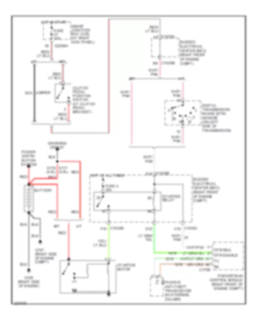
Starting Wiring Diagram for Ford Mustang GT 2006
List of elements for Starting Wiring Diagram for Ford Mustang GT 2006:
- (4.0l)
- A/t
- Battery
- Bussed electrical center (bec) (right front of engine compt)
- C1035a a9
- C1035a c10
- C1035b b9
- C1035b e10
- C1035b f10
- C175b
- C2280h
- Charging circuit
- Clutch pedal position switch (at clutch pedal bracket)
- D12
- Digital transmission range (dtr) sensor (on left side of transmission)
- Fuse 10a
- Fuse 4 30a
- G106 (right side of engine)
- G107 (right side of engine compt)
- Hot at all times
- Hot in start
- Jumper nca
- M/t
- Power distri- bution system
- Powertrain control module (right front of engine compt)
- Red
- Rx passive anti-theft transceiver (in steering column)
- S117 s110 (4.6l)
- Smart junction box (cjb) (at right kick panel)
- Starter motor
- Starter relay
- Str enable
- Str req

 Čeština
 Dansk
Dansk Deutsch
 Ελληνικά
 English
 English
 Español
 Suomi
Suomi Français
 Français
 עברית
עברית Hrvatski
 Magyar
 Italiano
 日本語
日本語 한국어
한국어 Nederlands
 Polski
 Português
 Română
 Русский
 Slovenčina
 Slovenščina
 Svenska
 Türkçe
 中文 (中国)