TRANSMISSION
2.5L
2.5L, A/T Wiring Diagram, Except Hybrid (1 of 2) for Ford Fusion S 2010
 https://portal-diagnostov.com/license.html
Automotive Electricians Portal FZCO
Automotive Electricians Portal FZCO
https://portal-diagnostov.com/license.html
https://portal-diagnostov.com/license.html
Automotive Electricians Portal FZCO
Automotive Electricians Portal FZCO
List of elements for 2.5L, A/T Wiring Diagram, Except Hybrid (1 of 2) for Ford Fusion S 2010:
- (2.5l: engine control sensor & fuel charge harness, near breakout to fuel injector 1) (3.0l: engine control sensor & fuel charge harness, near breakout to coil on plug 1)
- (battery cable wire harness, near breakout to automatic transmission)
- (engine control sensor & fuel charge wire harness, near breakout to c133)
- 6f transmission
- Accelerator pedal position (app) sensor (left side of dash)
- Battery junction box (bjb) (left side of engine compt)
- Brake pedal position switch (left side of dash)
- C1520a
- C1520b
- C2280d
- Cet05
- Cet06
- Cet07
- Cet08
- Cet09
- Cet10
- Cet18
- Cet25
- Cylinder head temperature (cht) sensor (top of engine)
- Electronic throttle control (etc) motor (top rear of engine)
- Engine controls system
- Exterior lights system
- Floor shifter
- Fuse 10a
- Fuse 15a
- Heated oxygen sensor (ho2s) 11 (2.5l: exhaust manifold) (3.0l: right exhaust manifold)
- Hot at all times
- Hot in start or run
- Le111
- Lpc vfs
- Oss
- Re406
- Ret24
- S138
- S142 (dash panel to headlamp junction harness, near breakout to powertrain control module)
- S146
- S147
- S181
- S251
- Smart junction box (sjb) (left side of dash)
- Sol pwr
- Ssa cb1234 vfs
- Ssb c35r vfs
- Ssc cb26 vfs
- Ssd cblr/cb456 vfs
- Sse on/off sol
- Tcc vfs
- Tft
- Tft sig rtn
- Trans- mission control switch
- Trs
- Trs/oss gnd
- Trs/oss pwr
- Tss
- Tss gnd
- Tss pwr
- Vet26
- Vet27
- Vet32
- Vet33
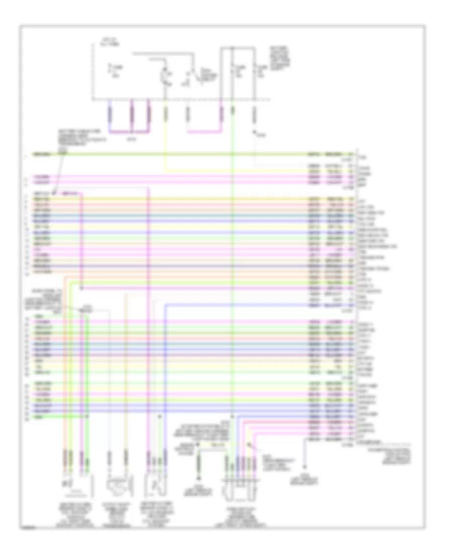
2.5L, A/T Wiring Diagram, Except Hybrid (2 of 2) for Ford Fusion S 2010
List of elements for 2.5L, A/T Wiring Diagram, Except Hybrid (2 of 2) for Ford Fusion S 2010:
- (2.5l) s182
- (battery cable wire harness, near breakout to automatic transmission) (3.0l) s148
- (dash panel to headlamp junction harness, near breakout to battery junction box)
- (w/ low emission vehicles) (3.0l: exhaust system)
- 15a
- 40a
- App1
- App1rtn
- App1vref
- App2
- App2rtn
- App2vref
- Battery junction box (bjb) (left side of engine compt)
- Bpp
- Bps
- C175b
- C175e
- C175t
- Cbb46
- Ccb08
- Ce233
- Ce234
- Ce235
- Ce302
- Ce412
- Ce426
- Ces09
- Cet05
- Cet06
- Cet07
- Cet08
- Cet09
- Cet10
- Cet18
- Cet25
- Cet34
- Cht
- Engine controls system
- Etcref
- Etcrtn
- Fuse
- G102 (left rear of engine compt)
- Gd120
- Heated oxygen sensor (ho2s) 12 (2.5l: exhaust manifold 3.0l: right side exhaust manifold)
- Heated oxygen sensor (ho2s) 13
- Ho2s 11
- Ho2s 12
- Ho2s 13
- Hot at all times
- Htr 11
- Htr 12
- Htr 13
- Iat
- Le111
- Le134
- Le136
- Le137
- Lpc vfs
- Maf
- Mafrtn
- Mass air flow/ intake air temperature (maf/iat) sensor (left front of eng compt)
- Oss
- Output shaft speed (oss) sensor (2.5l m/t) (top of transmission)
- Pcm power relay
- Pcmrc
- Power gnd
- Powertrain control module (pcm) (left rear of engine compt)
- Re134
- Re136
- Re137
- Re325
- Re405
- Re406
- Re407
- Ret24
- S125
- S140 (starter motor relay & battery ground harness, near breakout to battery junction box (bjb))
- S143
- S157 (near breakout to battery junction box)
- Sigrtnc
- Sigrtne
- Sol pwr
- Ssa cb1234 vfs
- Ssb c35r vfs
- Ssc cb26 vfs
- Ssd cblr/cb456 vfs
- Sse on/off sol
- Tacm +
- Tacm -
- Tcc vfs
- Tcs
- Tft
- Tft sig rtn
- Tp1 ns
- Tp2 ps
- Trs
- Trs/oss pwr
- Tss
- Tss/oss tr gnd
- Ve701
- Ve702
- Ve712
- Ve731
- Ve733
- Ve735
- Ve740
- Ve806
- Ve808
- Ve818
- Ve819
- Vet26
- Vet27
- Vet32
- Vet33
- Vpwr
2.5L, A/T Wiring Diagram, Hybrid for Ford Fusion S 2010
List of elements for 2.5L, A/T Wiring Diagram, Hybrid for Ford Fusion S 2010:
- (dash panel to headlamp junction harness, near breakout to battery junction box) s193
- (dash panel to headlamp junction harness, near breakout to bjb) s194
- (isdn1)
- (isdn2)
- 10a
- 40a
- Auxiliary relay box (left front of engine compt)
- Battery energy control module (becm) (behind left side of rear seat)
- Battery junction box (bjb) (left side of engine compt)
- Bussed electrical center (behind rear seat)
- C1458a
- C1458b
- C1458c
- C175b
- C175t
- C4236b
- C4237a
- Cbb39
- Ce302
- Computer data
- Computer data lines system
- Cto
- Cyb16
- Cyb17
- Cybo3
- Cybo4
- Cyt08
- Engine controls system
- Fuse
- G103 (left front of engine compt)
- Gd121
- Gmsdn
- Gnd
- Hot at all times
- Hs can+
- Hs can-
- Hv+
- Hv-
- Hvi+
- Hvi-
- Hyt03
- Hyt04
- Let56
- Let57
- Lines system
- Mect
- Motor electronics coolant temperature (mect) sensor (on transaxle)
- Pcm power relay
- Pcmrc
- Powertrain control module (pcm) (left rear of engine compt)
- Re406
- Ret56
- Ret57
- S119
- S143
- Sbb23
- Sigrtn
- Tgac
- Tmac
- Tr a1
- Tr a1rtn
- Tr a1vref
- Tr a2
- Tr a2rtn
- Tr a2vref
- Transaxle control module (on transaxle)
- Transmission range (tr) sensor (on transaxle)
- Vbatt
- Vdb04
- Vdb05
- Ve810
- Vet56
- Vet57
- Vmc02
- Vpwr
- Vyt05
- Vyt06
3.0L
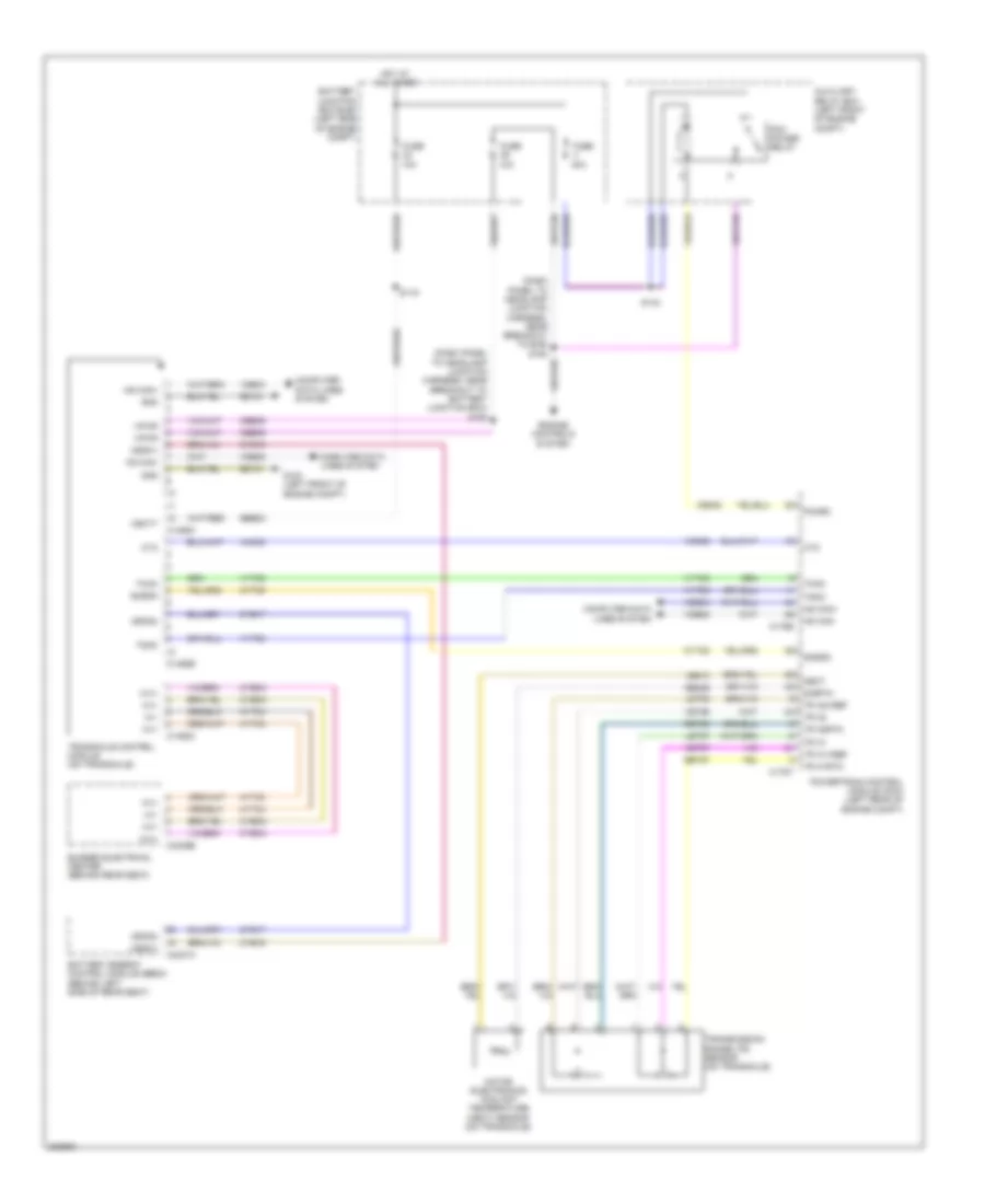
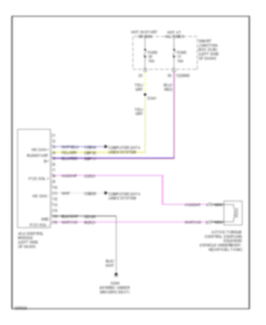
3.0L, 4WD Wiring Diagram for Ford Fusion S 2010
List of elements for 3.0L, 4WD Wiring Diagram for Ford Fusion S 2010:
- 4x4 control module (left side of dash)
- Active torque control coupling solenoid (vehicle underbody, near fuel tank)
- C2280d
- Cbp35
- Ccf21
- Computer data lines system
- Fuse 10a
- G300 (hybrid: under driver's seat)
- Gd126
- Gnd
- Hot at all times
- Hot in start or run
- Hs can +
- Hs can -
- Itcc sol +
- Itcc sol -
- Nca
- Rcf21
- Run/start
- S341
- Sbp11
- Smart junction box (sjb) (left side of dash)
- Vdb04
- Vdb05
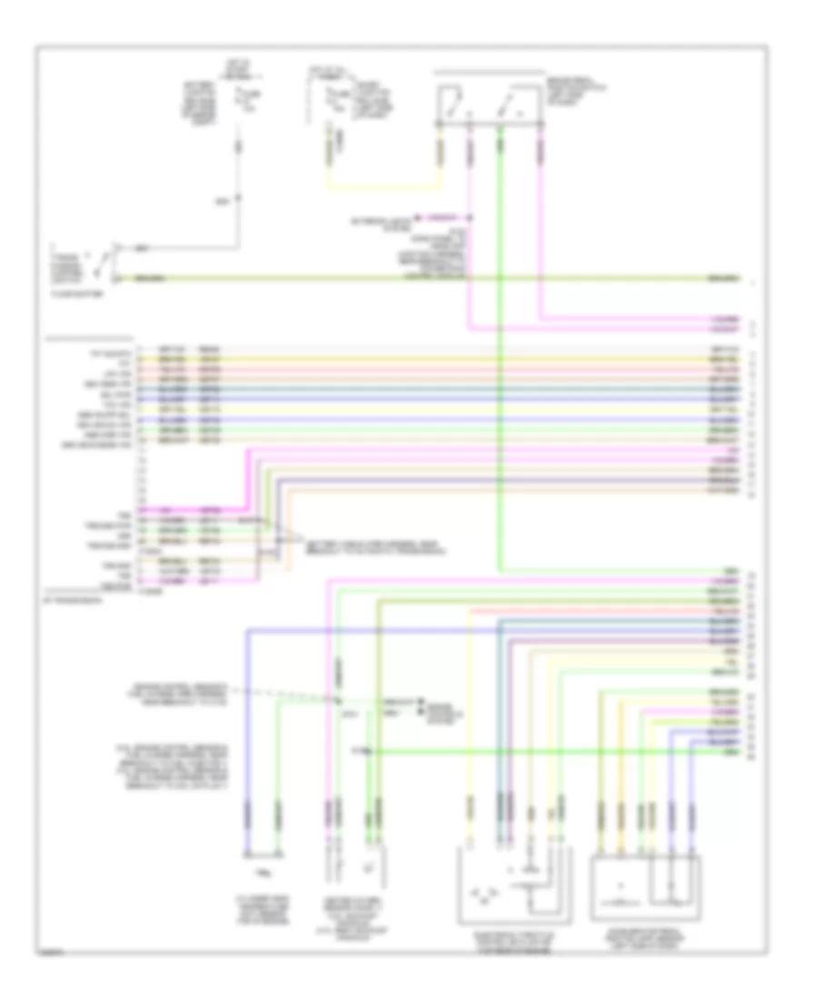
3.0L, A/T Wiring Diagram (1 of 2) for Ford Fusion S 2010
List of elements for 3.0L, A/T Wiring Diagram (1 of 2) for Ford Fusion S 2010:
- (2.5l: engine control sensor & fuel charge harness, near breakout to fuel injector 1) (3.0l: engine control sensor & fuel charge harness, near breakout to coil on plug 1)
- (battery cable wire harness, near breakout to automatic transmission)
- (engine control sensor & fuel charge wire harness, near breakout to c133)
- 6f transmission
- Accelerator pedal position (app) sensor (left side of dash)
- Battery junction box (bjb) (left side of engine compt)
- Brake pedal position switch (left side of dash)
- C1520a
- C1520b
- C2280d
- Cet05
- Cet06
- Cet07
- Cet08
- Cet09
- Cet10
- Cet18
- Cet25
- Cylinder head temperature (cht) sensor (top of engine)
- Electronic throttle control (etc) motor (top rear of engine)
- Engine controls system
- Exterior lights system
- Floor shifter
- Fuse 10a
- Fuse 15a
- Heated oxygen sensor (ho2s) 11 (2.5l: exhaust manifold) (3.0l: right exhaust manifold)
- Hot at all times
- Hot in start or run
- Le111
- Lpc vfs
- Oss
- Re406
- Ret24
- S138
- S142 (dash panel to headlamp junction harness, near breakout to powertrain control module)
- S146
- S147
- S181
- S251
- Smart junction box (sjb) (left side of dash)
- Sol pwr
- Ssa cb1234 vfs
- Ssb c35r vfs
- Ssc cb26 vfs
- Ssd cblr/cb456 vfs
- Sse on/off sol
- Tcc vfs
- Tft
- Tft sig rtn
- Trans- mission control switch
- Trs
- Trs/oss gnd
- Trs/oss pwr
- Tss
- Tss gnd
- Tss pwr
- Vet26
- Vet27
- Vet32
- Vet33
3.0L, A/T Wiring Diagram (2 of 2) for Ford Fusion S 2010
List of elements for 3.0L, A/T Wiring Diagram (2 of 2) for Ford Fusion S 2010:
- (2.5l) s182
- (battery cable wire harness, near breakout to automatic transmission) (3.0l) s148
- (dash panel to headlamp junction harness, near breakout to battery junction box)
- (w/ low emission vehicles) (3.0l: exhaust system)
- 15a
- 40a
- App1
- App1rtn
- App1vref
- App2
- App2rtn
- App2vref
- Battery junction box (bjb) (left side of engine compt)
- Bpp
- Bps
- C175b
- C175e
- C175t
- Cbb46
- Ccb08
- Ce233
- Ce234
- Ce235
- Ce302
- Ce412
- Ce426
- Ces09
- Cet05
- Cet06
- Cet07
- Cet08
- Cet09
- Cet10
- Cet18
- Cet25
- Cet34
- Cht
- Engine controls system
- Etcref
- Etcrtn
- Fuse
- G102 (left rear of engine compt)
- Gd120
- Heated oxygen sensor (ho2s) 12 (2.5l: exhaust manifold 3.0l: right side exhaust manifold)
- Heated oxygen sensor (ho2s) 13
- Ho2s 11
- Ho2s 12
- Ho2s 13
- Hot at all times
- Htr 11
- Htr 12
- Htr 13
- Iat
- Le111
- Le134
- Le136
- Le137
- Lpc vfs
- Maf
- Mafrtn
- Mass air flow/ intake air temperature (maf/iat) sensor (left front of eng compt)
- Oss
- Output shaft speed (oss) sensor (2.5l m/t) (top of transmission)
- Pcm power relay
- Pcmrc
- Power gnd
- Powertrain control module (pcm) (left rear of engine compt)
- Re134
- Re136
- Re137
- Re325
- Re405
- Re406
- Re407
- Ret24
- S125
- S140 (starter motor relay & battery ground harness, near breakout to battery junction box (bjb))
- S143
- S157 (near breakout to battery junction box)
- Sigrtnc
- Sigrtne
- Sol pwr
- Ssa cb1234 vfs
- Ssb c35r vfs
- Ssc cb26 vfs
- Ssd cblr/cb456 vfs
- Sse on/off sol
- Tacm +
- Tacm -
- Tcc vfs
- Tcs
- Tft
- Tft sig rtn
- Tp1 ns
- Tp2 ps
- Trs
- Trs/oss pwr
- Tss
- Tss/oss tr gnd
- Ve701
- Ve702
- Ve712
- Ve731
- Ve733
- Ve735
- Ve740
- Ve806
- Ve808
- Ve818
- Ve819
- Vet26
- Vet27
- Vet32
- Vet33
- Vpwr
3.5L
3.5L, 4WD Wiring Diagram for Ford Fusion S 2010
List of elements for 3.5L, 4WD Wiring Diagram for Ford Fusion S 2010:
- 4x4 control module (left side of dash)
- Active torque control coupling solenoid (vehicle underbody, near fuel tank)
- C2280d
- Cbp35
- Ccf21
- Computer data lines system
- Fuse 10a
- G300 (hybrid: under driver's seat)
- Gd126
- Gnd
- Hot at all times
- Hot in start or run
- Hs can +
- Hs can -
- Itcc sol +
- Itcc sol -
- Nca
- Rcf21
- Run/start
- S341
- Sbp11
- Smart junction box (sjb) (left side of dash)
- Vdb04
- Vdb05
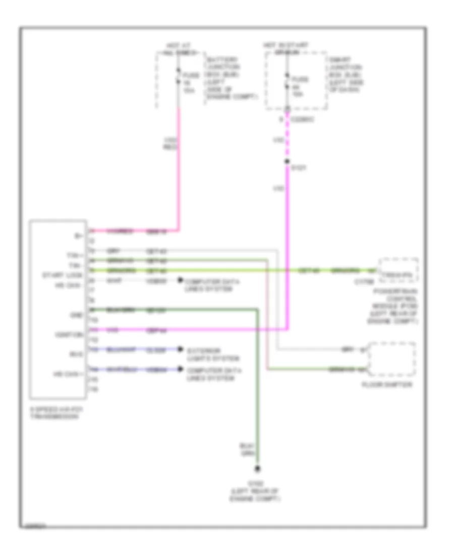
3.5L, A/T Wiring Diagram for Ford Fusion S 2010
List of elements for 3.5L, A/T Wiring Diagram for Ford Fusion S 2010:
- 6 speed aw-f21 transmission
- Battery junction box (bjb) (left side of engine compt)
- C175b
- C2280c
- Cbp44
- Cet40
- Cet42
- Cet43
- Cls28
- Computer data lines system
- Exterior lights system
- Floor shifter
- Fuse 10a
- Fuse 15a
- G102 (left rear of engine compt)
- Gd120
- Gnd
- Hot at all times
- Hot in start or run
- Hs can +
- Hs can -
- Ignition
- Powertrain control module (pcm) (left rear of engine compt)
- Rvs
- S121
- Sbb16
- Smart junction box (sjb) (left side of dash)
- Start lock
- Tin +
- Tin -
- Trsw-pn
- Vdb04
- Vdb05

 Čeština
 Dansk
Dansk Deutsch
 Ελληνικά
 English
 English
 Español
 Suomi
Suomi Français
 Français
 עברית
עברית Hrvatski
 Magyar
 Italiano
 日本語
日本語 한국어
한국어 Nederlands
 Polski
 Português
 Română
 Русский
 Slovenčina
 Slovenščina
 Svenska
 Türkçe
 中文 (中国)