ENGINE PERFORMANCE
1.8L
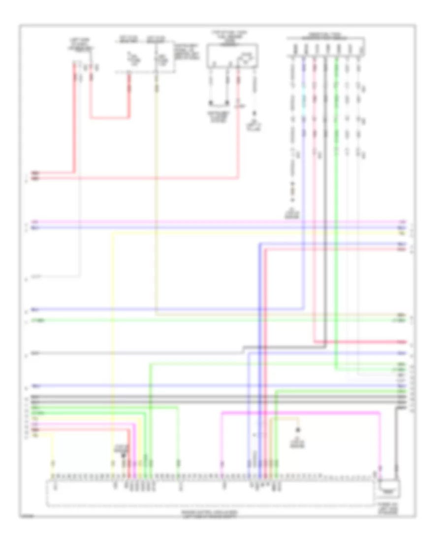
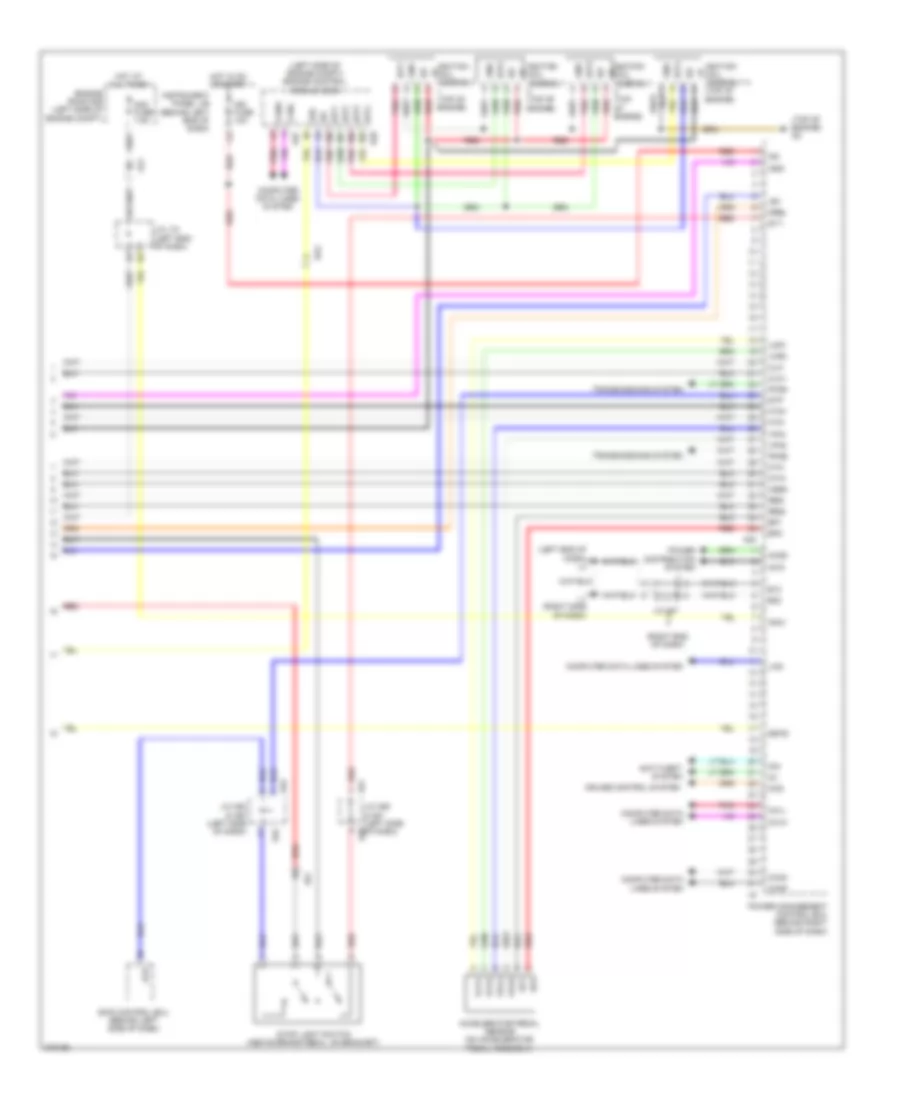
1.8L, Engine Controls Wiring Diagram (1 of 4) for Toyota Prius V 2013
 https://portal-diagnostov.com/license.html
Automotive Electricians Portal FZCO
Automotive Electricians Portal FZCO
https://portal-diagnostov.com/license.html
https://portal-diagnostov.com/license.html
Automotive Electricians Portal FZCO
Automotive Electricians Portal FZCO
List of elements for 1.8L, Engine Controls Wiring Diagram (1 of 4) for Toyota Prius V 2013:
- (left end of dash) j/c a56
- +b1
- +b2
- +bm
- A3 (left front of engine compt)
- A4 (left front of engine compt)
- A57
- Al1
- Al2
- Batt
- C/opn relay
- Camshaft timing oil control valve (intake) (front of cylinder head)
- Canh
- Canl
- Cann
- Canp
- Computer data line system
- Computer data lines system
- Cooling fans system
- D2 (top of engine)
- Da2
- Eco & ev & power mode switch (combination switch assembly)
- Efi 2 fuse 10a
- Efi main fuse 20a
- Efi main relay
- Egr valve (rear of engine)
- Egr1
- Egr2
- Egr3
- Egr4
- Eng w/p fuse 30a
- Eng w/p relay
- Engine control module (ecm) (left side of engine compt)
- Engine room j/b (left side of engine compt)
- Engine room r/b (left side of engine compt)
- Engine water pump assembly (right front of engine compt)
- Etcs fuse 10a
- Fanh
- Fanl
- Hot at all times
- Ig2 fuse 20a
- Ig2 relay
- Igsw
- J/c a56 (left end of dash)
- J/c l70 (left end of dash)
- J/c l71
- L3 (left end of dash)
- Mpmp
- Mrel
- Nwp
- Pgnd
- Pnk
- Pwms
- Red
- Swp
- Tach
- Vpmp
- Wpi
- Wpo
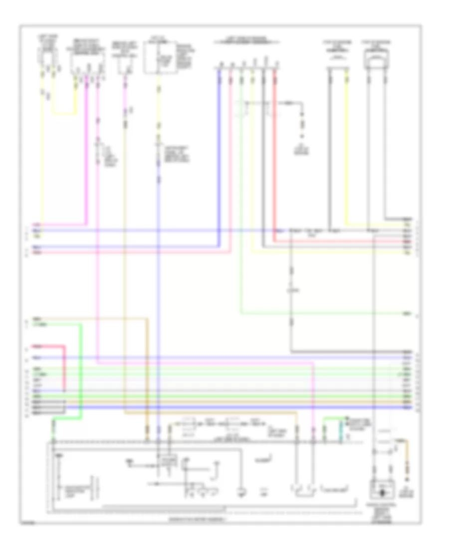
1.8L, Engine Controls Wiring Diagram (2 of 4) for Toyota Prius V 2013
List of elements for 1.8L, Engine Controls Wiring Diagram (2 of 4) for Toyota Prius V 2013:
- (left side of dash) j/c a52 & a53
- (near fuel tank) canister pump module
- (top of engine)
- (top of fuel tank) fuel sender gage assembly
- A44
- A52
- A53
- Ar1
- As1
- C13
- D1 (top of engine)
- D28
- Da1
- E04
- Egr1
- Egr2
- Egr3
- Egr4
- Engine control module (ecm) (left side of engine compt)
- G2o
- Ge01
- Ha1a
- Hot in on or start
- Ht1b
- Igf
- Ign fuse 10a
- Instrument cluster system
- Instrument panel j/b (behind left end of dash)
- Me01
- Met fuse 7.5a
- Mgnd
- Mtrb
- Oc1+
- Oc1-
- Pnk
- Prg
- Pump
- Purge vsv (left side of engine)
- R2 (left "c" pillar)
- Red
- Sgnd
- So1
- Vcc
- Vgnd
- Vlvb
- Vout
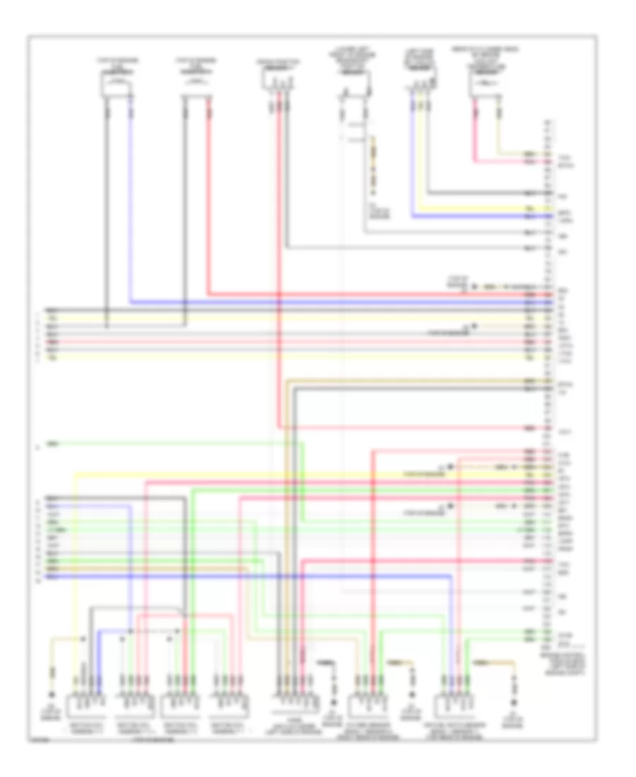
1.8L, Engine Controls Wiring Diagram (3 of 4) for Toyota Prius V 2013
List of elements for 1.8L, Engine Controls Wiring Diagram (3 of 4) for Toyota Prius V 2013:
- (behind left side of dash) skid control ecu
- (behind right side of dash) power management control ecu
- (left side of dash) j/c a52 & a53
- (left side of engine) throttle body assembly
- (top of engine) fuel injector 1
- (top of engine) fuel injector 2
- +5b
- +5v
- A21
- A22
- A37
- A52
- A53
- Al2
- Buzzer
- C18
- Can driver
- Combination meter assembly
- Computer data lines system
- D1 (top of engine)
- Da2
- Df1
- Ecu-b fuse 7.5a
- Engine room r/b (left side of engine compt)
- Hot at all times
- I/f
- Ig2d
- Ign2
- Instrument panel j/b (behind left end of dash)
- J/c l70 (left end of dash)
- J/c l71
- Knock control sensor (bank 1) (left side of engine)
- L27
- L3 (left end of dash)
- Malfunction indicator lamp
- Nca
- Pnk
- Red
- Sp1
- Spdi
- Vta
- Vta2
1.8L, Engine Controls Wiring Diagram (4 of 4) for Toyota Prius V 2013
List of elements for 1.8L, Engine Controls Wiring Diagram (4 of 4) for Toyota Prius V 2013:
- (left side of engine) efi vacuum sensor
- (lower left front of engine) crankshaft position sensor
- (rear of cylinder head) efi engine coolant temperature sensor
- (top of engine)
- (top of engine) d1
- (top of engine) fuel injector 3
- (top of engine) fuel injector 4
- A1a+
- A1a-
- Air fuel ratio sensor (bank 1 sensor 1) (top rear of engine)
- Crank position sensor 1
- D1 (top of engine)
- D2 (top of engine)
- D28
- E01
- E02
- E03
- E2g
- Eknk
- Engine control module (ecm) (left side of engine compt)
- Epim
- Eppm
- Eta
- Etha
- Ethw
- G2+
- G2-
- Gnd
- Ha1a
- Ht1b
- Igf
- Ignition coil assembly 1
- Ignition coil assembly 2
- Ignition coil assembly 3
- Ignition coil assembly 4
- Igt1
- Igt2
- Igt3
- Igt4
- Knk1
- Mass air flow meter (left side of engine)
- Nca
- Ne+
- Ne-
- O1b-
- Ox1b
- Oxygen sensor (bank 1 sensor 2) (right rear of engine)
- Pim
- Pnk
- Ppmp
- Red
- Tha
- Thw
- Vcpm
- Vcpp
- Vcta
- Vcv1
- Vta1
- Vta2
- Vvi+
- Vvi-
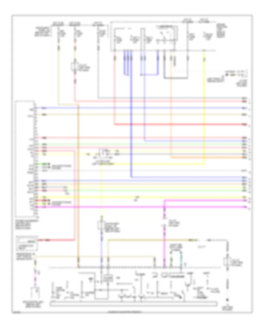
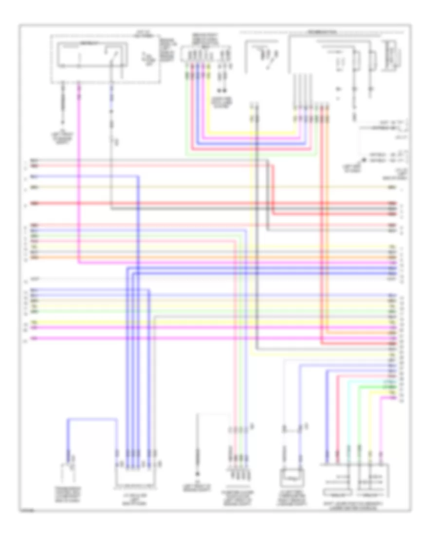
1.8L, Hybrid System Wiring Diagram (1 of 6) for Toyota Prius V 2013
List of elements for 1.8L, Hybrid System Wiring Diagram (1 of 6) for Toyota Prius V 2013:
- +5b
- +5v
- +b2
- +batt
- A21
- A3 (left front of engine compt)
- A32
- A37
- A44
- A52
- A53
- Air conditioning system
- Al2
- As1
- Bkup
- Buzzer
- C11
- C18
- Can driver
- Charge ind
- Clk
- Combination meter assembly
- Computer data lines system
- Da1
- Ecu-b fuse 7.5a
- Engine room j/b (left side of engine compt)
- Engine room r/b (left side of engine compt)
- Eti
- Ev mode
- Fctl
- G13
- Gmt
- Gmtg
- Hot at all times
- Hot in on or start
- Hv system ind
- I/f
- Igct 2 fuse 10a
- Igct 3 fuse 10a
- Igct fuse 30a
- Igct relay
- Ign fuse 10a
- Ign2
- Ilk
- Instrument panel j/b (behind left end of dash)
- Integration relay
- Ite
- Iwp
- J/c a52 & a53 (left side of dash)
- J/c a56 (left end of dash)
- J/c l70 (left end of dash)
- J/c l71
- L27
- L3 (left end of dash)
- Met fuse 7.5a
- Mmt
- Mmtg
- Niwp
- Nodd
- Over heated hv unit ind
- P lock failure
- Pcu fuse 10a
- Pnk
- Power management control ecu (behind right side of dash)
- Ready
- Red
- Shift by wire p lock failure
- Sio
- Skid control ecu (behind left side of dash)
- Sp1
- Stb
- Stop fuse 10a
- Vlo
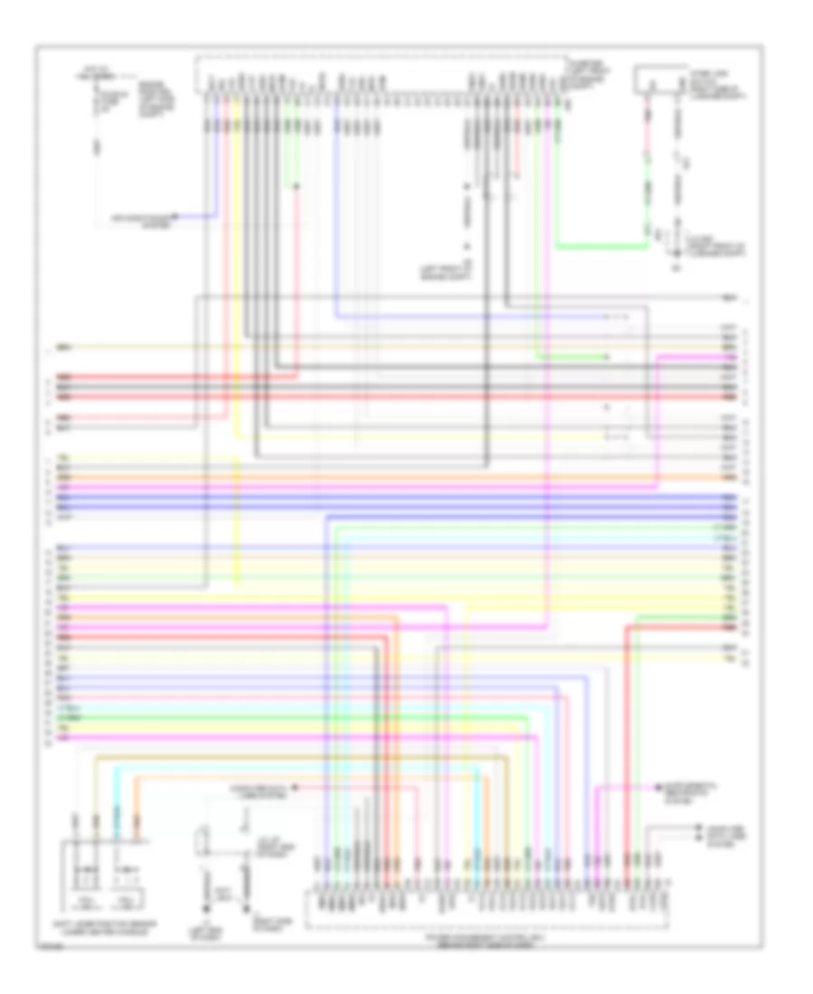
1.8L, Hybrid System Wiring Diagram (2 of 6) for Toyota Prius V 2013
List of elements for 1.8L, Hybrid System Wiring Diagram (2 of 6) for Toyota Prius V 2013:
- (behind right side of dash) certification ecu
- +bwp
- A23
- A3 (left front of engine compt)
- A4 (left front of engine compt)
- A54
- A55
- Agnd
- Ag1
- Canh
- Canl
- Code
- Computer data lines system
- Da2
- Engine room j/b (left side of engine compt)
- Gnd
- Hall ic
- Hot at all times
- Hv battery thermometer (right rear of luggage compt)
- Ig2 fuse 20a
- Ig2 relay
- Inverter water pump motor (left front of engine compt)
- J/c a54 & a55 (left end of dash)
- J/c l70 (left end of dash)
- J/c l71
- L3 (left end of dash)
- L62
- Ls1
- Nwp
- Pnk
- Power switch
- Red
- Shift lever position sensor 2 (under center console)
- Ss1
- Ss2
- Swil
- Swp
- Transmission control ecu (lower right end of dash)
- Transponder key coil
- Txct
- Vc5
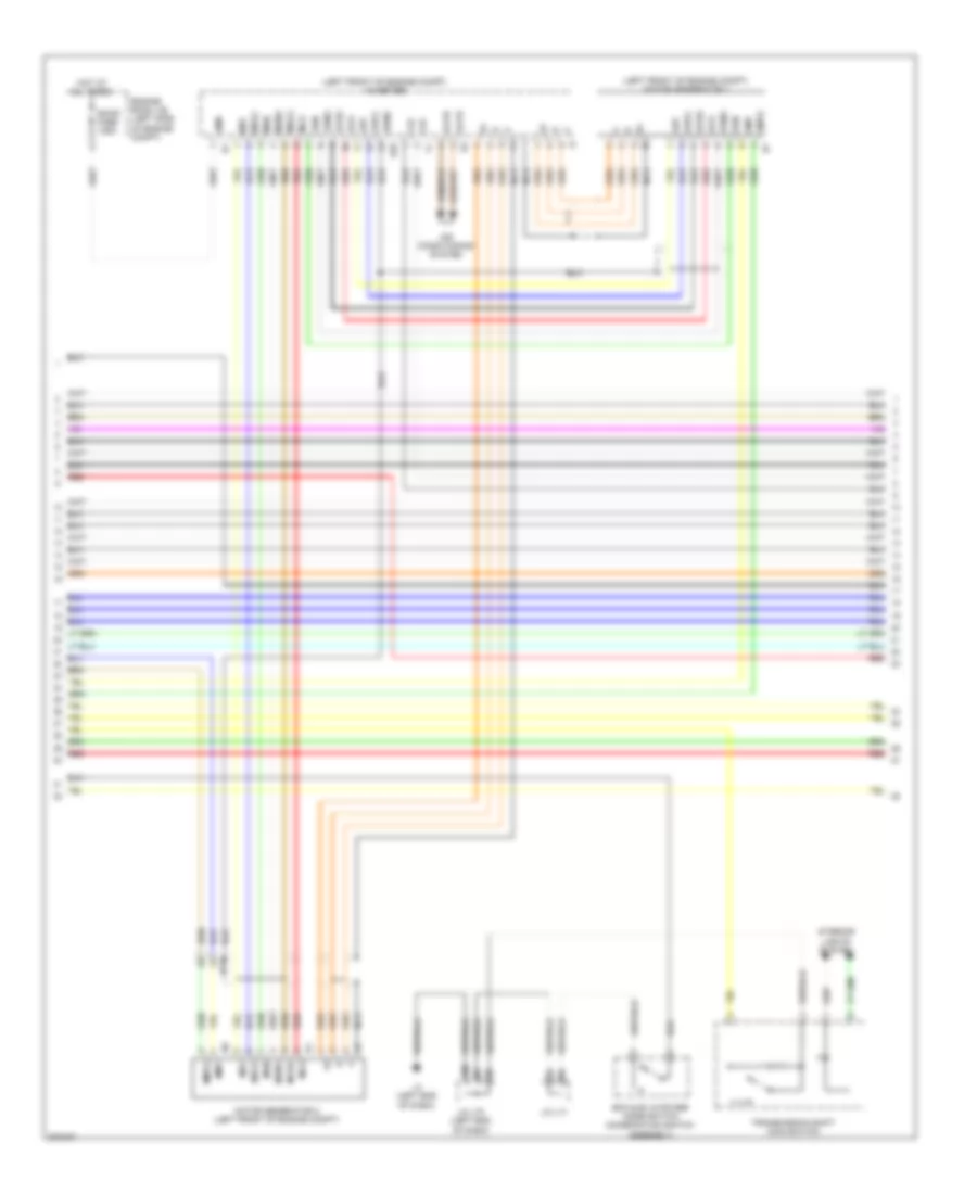
1.8L, Hybrid System Wiring Diagram (3 of 6) for Toyota Prius V 2013
List of elements for 1.8L, Hybrid System Wiring Diagram (3 of 6) for Toyota Prius V 2013:
- +b2
- A4 (left front of engine compt)
- A59
- Abfs
- Air conditioning system
- Am22
- As1
- Bth+
- Bth-
- Ca2h
- Ca2l
- Clk+
- Clk-
- Computer data lines system
- Dc/dc-s fuse 5a
- Drn1
- Drn2
- Drn3
- Drn4
- Drn5
- Drn8
- E01
- E2x1
- E2x2
- Engine room r/b (left side of engine compt)
- Ethb
- Evsw
- Gnd
- Gnd1
- Gnd2
- Hall ic
- Hot at all times
- Hsdn
- Htm+
- Htm-
- Idh
- Igct
- Ilk
- Ilki
- Ilko
- Inds
- Indw
- Inter lock switch (right side of luggage compt)
- Inverter (left front of engine compt)
- J/c l87 (right end of dash)
- J/c s20 (right front of luggage compt)
- L1 (right side of dash)
- L3 (left end of dash)
- Mth+
- Mth-
- Nodd
- Pnk
- Power management control ecu (behind right side of dash)
- Red
- Req+
- Req-
- Shift lever position sensor (under center console)
- Smrb
- Smrg
- Smrp
- Spdi
- Ssw1
- Sc1
- Thb
- Vcx1
- Vcx2
- Vcx3
- Vcx4
- Vlo
- Vsx1
- Vsx2
- Vsx3
- Vsx4
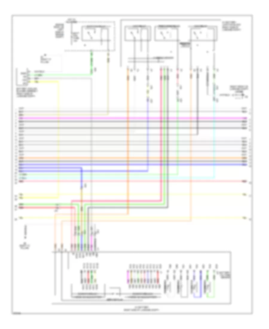
1.8L, Hybrid System Wiring Diagram (4 of 6) for Toyota Prius V 2013
List of elements for 1.8L, Hybrid System Wiring Diagram (4 of 6) for Toyota Prius V 2013:
- (left front of engine compt) inverter
- (left front of engine compt) motor generator 1
- Acpb
- Acpe
- Air conditioning system
- Amd
- Cbi
- Cei
- D29
- Da1
- Dc/dc fuse 125a
- Drn6
- Eco & ev & power mode switch (combination switch assembly)
- Engine room j/b (left side of engine compt)
- Gcs
- Gcsg
- Gmt
- Gmtg
- Grf
- Grfg
- Gsn
- Gsng
- Hot at all times
- Interior lights system
- J/c l70 (left end of dash)
- J/c l71
- L3 (left end of dash)
- Mcs
- Mcsg
- Mmt
- Mmtg
- Motor generator 2 (left front of engine compt)
- Mrf
- Mrfg
- Mscg
- Msn
- Msng
- Nca
- Red
- Transmission shift main switch
1.8L, Hybrid System Wiring Diagram (5 of 6) for Toyota Prius V 2013
List of elements for 1.8L, Hybrid System Wiring Diagram (5 of 6) for Toyota Prius V 2013:
- (right front of luggage compt) j/c s20
- As1
- Batt fan fuse 10a
- Batt fan relay
- Battery cooling blower assembly (right side of luggage compt)
- Battery voltage sensor
- Bth+
- Bth-
- Busbar module 1
- Busbar module 2
- Current sensor
- Engine room j/b (left side of engine compt)
- Gb0
- Gb1
- Gb2
- Gc0
- Gib
- Gnd
- Gnd0
- Hot at all times
- Hv battery (right side of luggage compt)
- Hv battery junction block (right side of luggage compt)
- Hybrid vehicle battery
- Ig0
- Igct
- Ls1
- Main relay
- Pnk
- Pnk vb4
- Precharge relay
- Red
- Red gb0
- Red vb12
- Resistor
- S1 (right "c" pillar)
- S2 (right "c" pillar)
- Service plug
- Si0
- Sc1
- Tb0
- Tb1
- Tb2
- Tc0
- Thermistor
- Vb2
- Vb5
- Vc1 j1
- Vc10
- Vc11
- Vc12
- Vc13
- Vc14
- Vc2
- Vc3
- Vc4
- Vc5
- Vc6
- Vc7
- Vc8
- Vc9
- Vib
- Vm0
- Z17
1.8L, Hybrid System Wiring Diagram (6 of 6) for Toyota Prius V 2013
List of elements for 1.8L, Hybrid System Wiring Diagram (6 of 6) for Toyota Prius V 2013:
- (left end of dash) l3
- (left side of engine compt) engine control module (ecm)
- (right end of dash)
- (top of engine) d2
- +b1
- A22
- A51
- A52
- A53
- A57
- Accd
- Accelerator pedal sensor (on accelerator pedal assembly)
- Al2
- Am2 fuse 7.5a
- Am21
- Anti-theft system
- Ca1h
- Ca1l
- Ca3n
- Ca3p
- Canh
- Canl
- Ccs
- Clk+
- Clk-
- Computer data lines system
- Cruise control system
- D28
- Da2
- E02
- E12
- Engine room r/b (left side of engine compt)
- Ep1
- Ep2
- G2o
- Gnd
- Hot at all times
- Hot in on or start
- Hsdn
- Htm+
- Htm-
- Ig1d
- Ig2
- Ig2d
- Igf
- Ign fuse 10a
- Ignition coil +b assembly (top of engine)
- Ignition coil assembly (top of engine)
- Ignition coil assembly 4 (top of engine)
- Igt1
- Igt2
- Igt3
- Igt4
- Imi
- Imo
- Instrument panel j/b (behind left end of dash)
- J/c a50 & a51 (left side of dash) a50
- J/c a52 & a53 (left side of dash)
- J/c l70 (left end of dash)
- J/c l87
- L1 (right side of dash)
- Lin2
- Mrel
- Mth+
- Mth-
- Pcon
- Pnk
- Power distribution system
- Power management control ecu (behind right side of dash)
- Ppos
- Red
- Req+
- Req-
- Skid control ecu (behind left side of dash)
- Ssw2
- St1-
- Stop light switch (above brake pedal, on bracket)
- Stp
- Transmissions system
- Vcp1
- Vcp2
- Vpa1
- Vpa2

 Čeština
 Dansk
Dansk Deutsch
 Ελληνικά
 English
 English
 Español
 Suomi
Suomi Français
 Français
 עברית
עברית Hrvatski
 Magyar
 Italiano
 日本語
日本語 한국어
한국어 Nederlands
 Polski
 Português
 Română
 Русский
 Slovenčina
 Slovenščina
 Svenska
 Türkçe
 中文 (中国)