RADIO
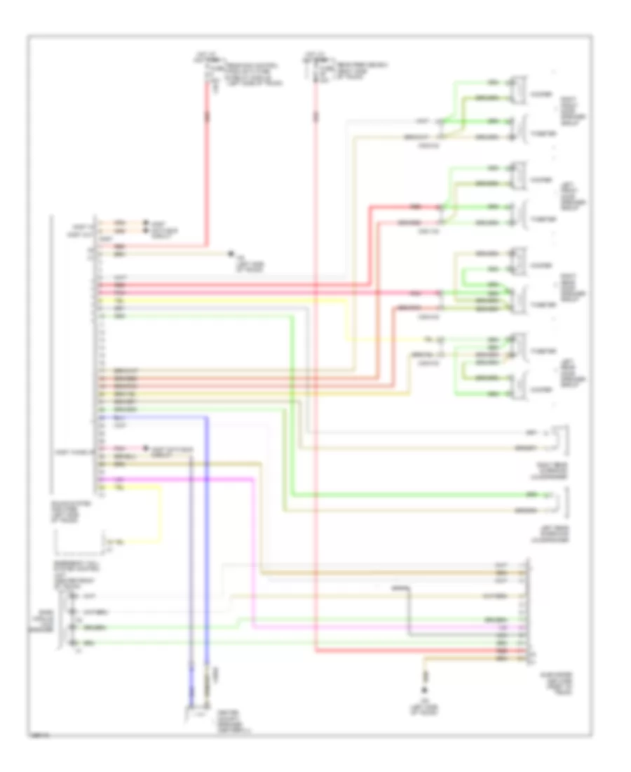
COMAND Actuation Wiring Diagram (1 of 2) for Mercedes-Benz CLS550 2011

List of elements for COMAND Actuation Wiring Diagram (1 of 2) for Mercedes-Benz CLS550 2011:
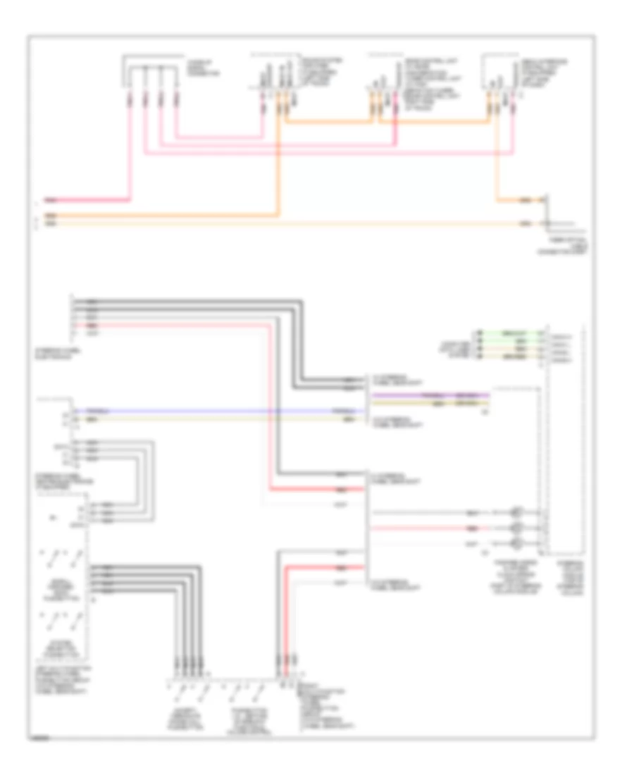
COMAND Actuation Wiring Diagram (2 of 2) for Mercedes-Benz CLS550 2011
List of elements for COMAND Actuation Wiring Diagram (2 of 2) for Mercedes-Benz CLS550 2011:
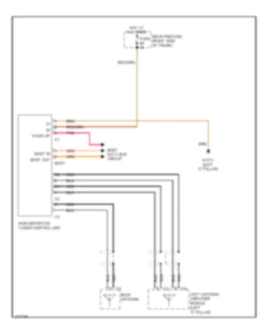
High Definition Tuner Wiring Diagram for Mercedes-Benz CLS550 2011
List of elements for High Definition Tuner Wiring Diagram for Mercedes-Benz CLS550 2011:
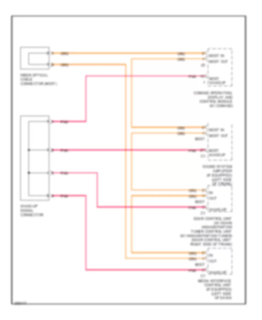
MOST Data Bus Wiring Diagram for Mercedes-Benz CLS550 2011
List of elements for MOST Data Bus Wiring Diagram for Mercedes-Benz CLS550 2011:
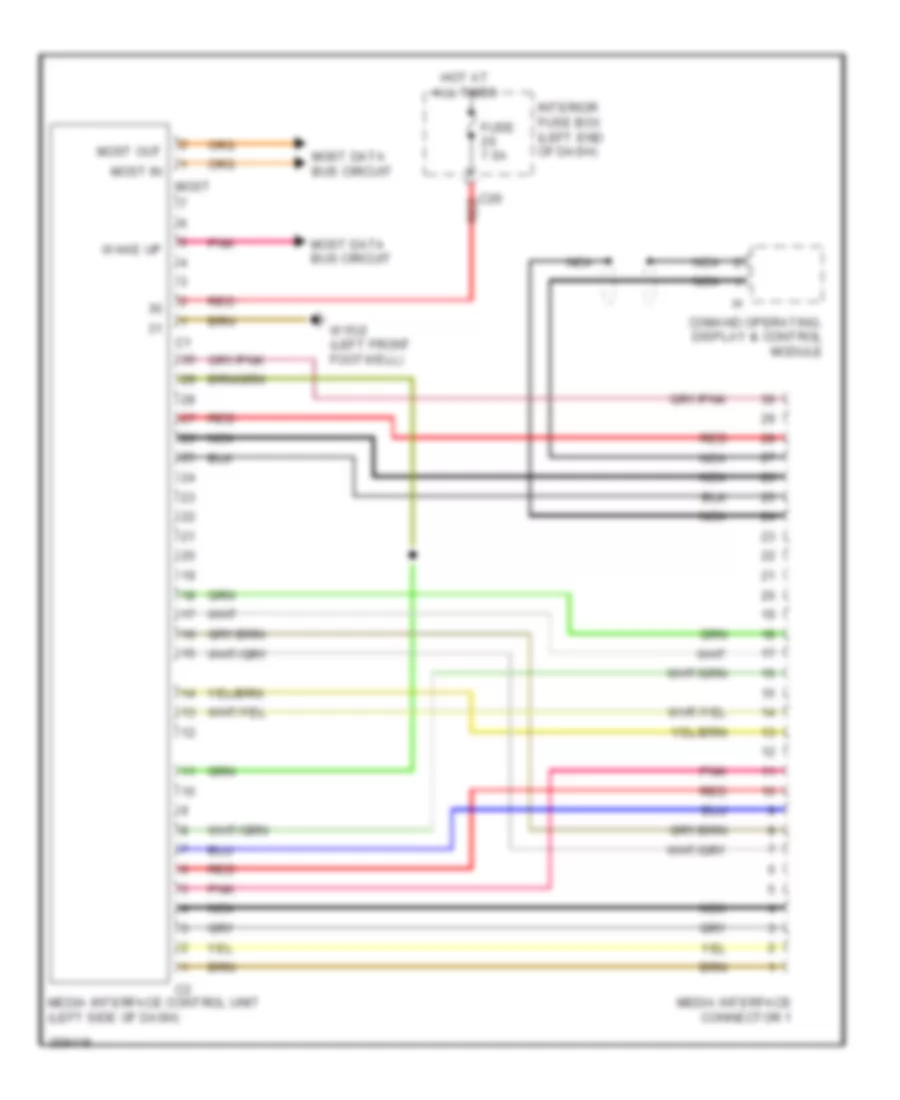
Multimedia Interface Wiring Diagram for Mercedes-Benz CLS550 2011
List of elements for Multimedia Interface Wiring Diagram for Mercedes-Benz CLS550 2011:
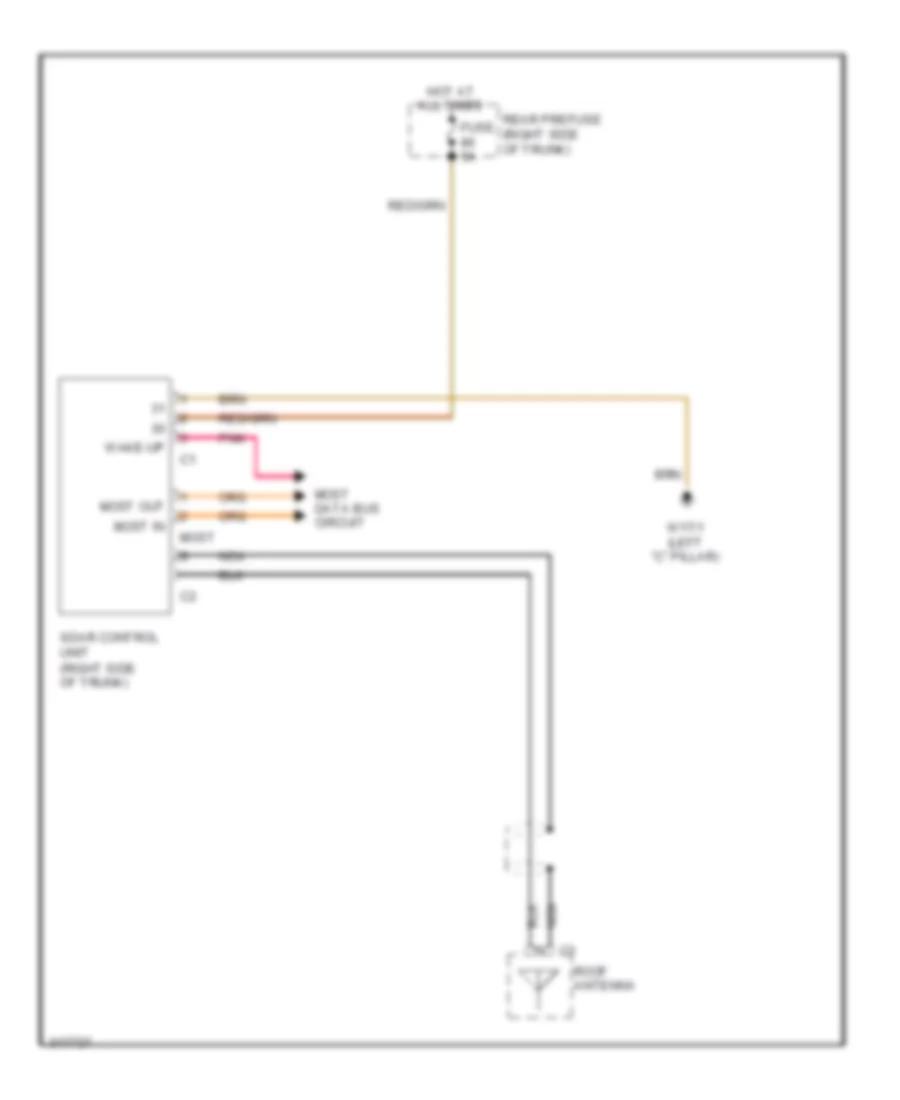
Satellite Radio Wiring Diagram for Mercedes-Benz CLS550 2011
List of elements for Satellite Radio Wiring Diagram for Mercedes-Benz CLS550 2011:
Sound Amplifier Wiring Diagram for Mercedes-Benz CLS550 2011
List of elements for Sound Amplifier Wiring Diagram for Mercedes-Benz CLS550 2011: