STARTING/CHARGING
Charging Wiring Diagram for Audi Q5 Premium 2013
 https://portal-diagnostov.com/license.html
Automotive Electricians Portal FZCO
Automotive Electricians Portal FZCO
https://portal-diagnostov.com/license.html
https://portal-diagnostov.com/license.html
Automotive Electricians Portal FZCO
Automotive Electricians Portal FZCO
List of elements for Charging Wiring Diagram for Audi Q5 Premium 2013:
- (left side of luggage compt) battery monitoring control module
- 2.0l
- 3.0l
- Battery
- Battery interrupt igniter
- Battery jump start terminal (terminal 30 wire junction 2) (in center plenum chamber)
- Computer data lines system
- Data bus on board diagnostic interface
- Fuse panel a (on battery positive terminal)
- G624 (in luggage compt near starter battery)
- Generator & voltage regulator
- Instrument cluster control module
- Starter
- T17e
- T17r
- T5l
- Voltage stabilizer (w/ start/stop system) (right side of luggage compt)
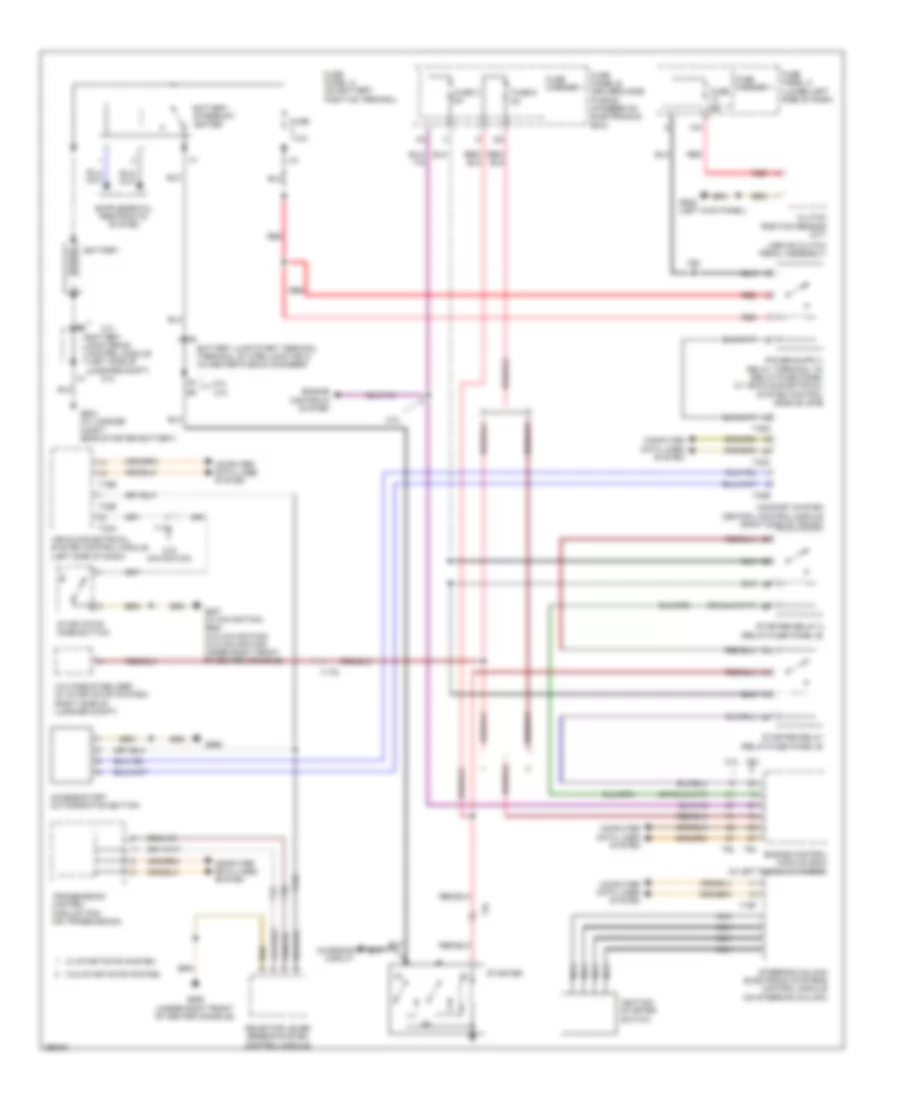
Starting Wiring Diagram for Audi Q5 Premium 2013
List of elements for Starting Wiring Diagram for Audi Q5 Premium 2013:
- (above clutch pedal assembly)
- 10a
- 2.0l
- 3.0l
- 3.0l 2.0l
- Access/start authorization button
- Battery
- Battery interrupt igniter
- Battery jump start terminal (terminal 30 wire junction 2) (in center plenum chamber)
- Battery monitoring control module (left side of luggage compt)
- Charging circuit
- Clutch position sensor (m/t)
- Comfort system central control module (right side of trunk)
- Computer data lines system
- Engine control module (ecm) (in left plenum chamber)
- Engine controls system
- Fuse 110a
- Fuse 3 5a
- Fuse 5a
- Fuse 9 5a
- Fuse carrier 1
- Fuse panel a (on battery positive terminal)
- Fuse panel b (driver's side plenum chamber on electronics box)
- Fuse panel c (lower left side of dash)
- G624 (in luggage compt near starter battery)
- G639 (left kick panel)
- G668
- G688 (under right front of center console)
- G887 (w/ navigation) g688 (w/o navigation) (w/o navigation: under right front of center console)
- Ignition/ starter switch
- Navigation
- Nca
- Red
- Selector lever sensor system control module
- Start/stop mode button
- Starter
- Starter relay (relay/fuse panel b)
- Starter relay 2 (relay/fuse panel b)
- Steering column electronic systems control module (on steering column)
- T16b
- T16f
- T17c
- T17q
- T32a
- T32b
- T32c
- T32d
- T32e
- T5i
- T94
- Transmission control module (tcm) (on transmission)
- Vehicle electrical system control module (left side of dash)
- Voltage stabilizer (w/ start/stop system) (right side of luggage compt)
- W/ start/stop system
- W/o
- W/o start/stop system

 Čeština
 Dansk
Dansk Deutsch
 Ελληνικά
 English
 English
 Español
 Suomi
Suomi Français
 Français
 עברית
עברית Hrvatski
 Magyar
 Italiano
 日本語
日本語 한국어
한국어 Nederlands
 Polski
 Português
 Português
 Русский
 Slovenčina
 Slovenščina
 Svenska
 Türkçe
 中文 (中国)