INSTRUMENT CLUSTER
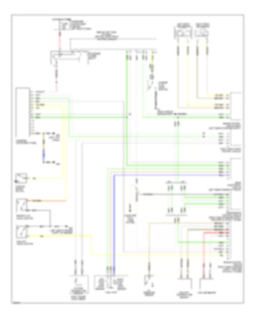
Instrument Cluster Wiring Diagram for Volvo S80 2004
List of elements for Instrument Cluster Wiring Diagram for Volvo S80 2004:
- (behind left side of dash) central electronic control module
- A/t
- Brake control module (bcm) (left rear of engine compt)
- Brake fluid level monitor
- Combined instrument panel
- Computer data lines system
- Coolant level monitor
- Coolant temperature sensor
- Engine control module (right side of engine compt, forward of strut tower)
- Extended x-feed relay
- Fuel pump
- Fuse c24 10a
- G1 (right side of engine compt, on fender)
- G83 (left kick panel)
- G93 (left side of engine compt, on fender)
- G98
- Hot at all times
- Impulse sensor
- Left front abs sensor
- Left pump fuel level sensor
- M/t
- Oil pressure sensor
- Outside temperature sensor
- Parking brake switch
- Passenger compartment fuse box (left end of dash)
- Rear electronic module (left rear corner of trunk)
- Red
- Right front abs sensor
- Right front door control module
- Right power door mirror
- Right pump fuel level sensor
- Transmission control module (right side of engine compt, forward of strut tower)
- Washer fluid level monitor
 Čeština
 Dansk
Dansk Deutsch
 Ελληνικά
 English
 English
 Español
 Suomi
Suomi Français
 Français
 עברית
עברית Hrvatski
 Magyar
 Italiano
 日本語
日本語 한국어
한국어 Nederlands
 Polski
 Português
 Português
 Русский
 Slovenčina
 Slovenščina
 Svenska
 Türkçe
 中文 (中国)
 Română