SUPPLEMENTAL RESTRAINTS
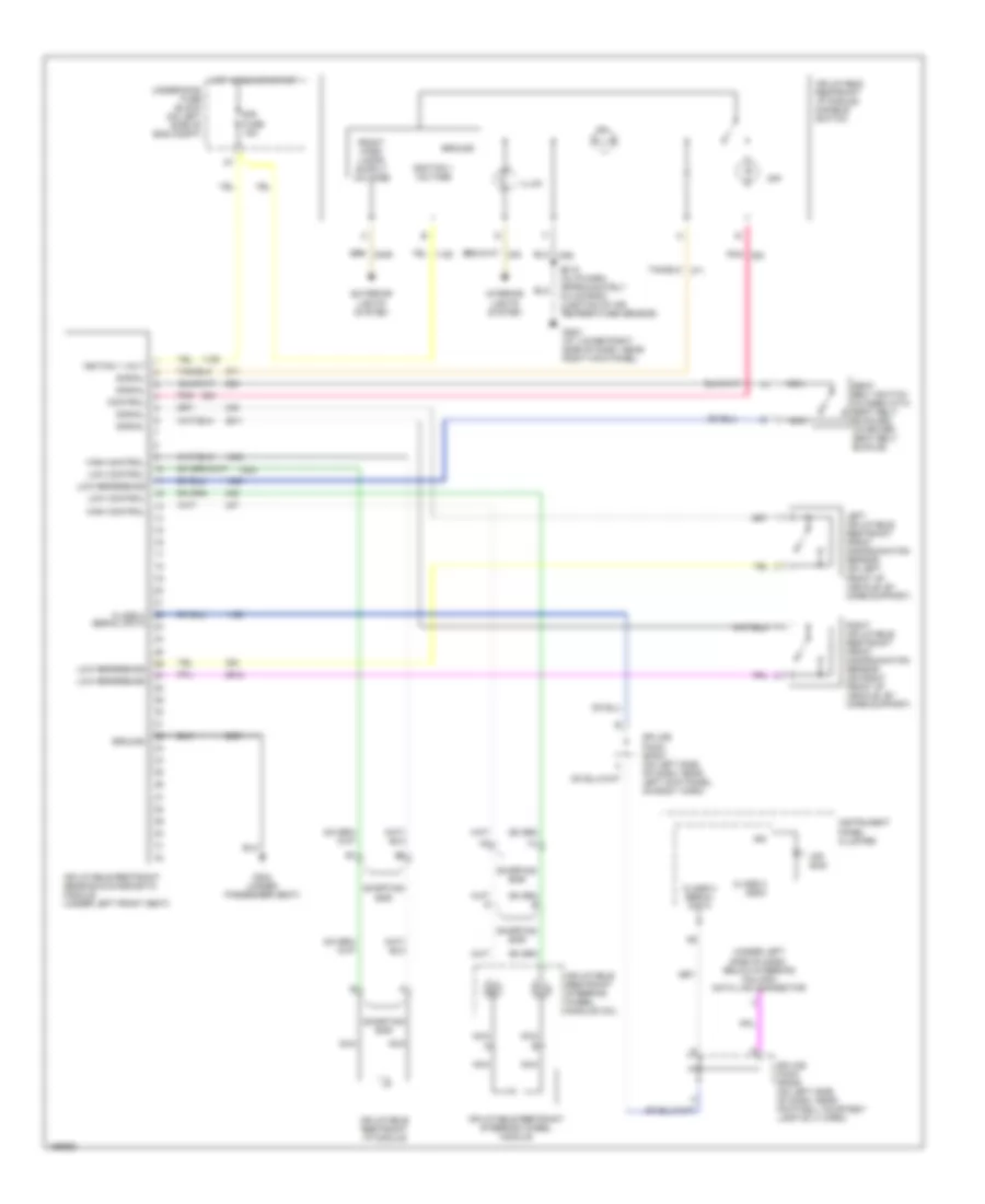
Supplemental Restraints Wiring Diagram for Hummer H2 2003
List of elements for Supplemental Restraints Wiring Diagram for Hummer H2 2003:
- (under left side of dash, below steering column) data link connector
- Air bag
- Class 2 (sdm)
- Class 2 serial data
- Control
- Exterior lights system
- G203 (at lower right side of dash, near right kick panel)
- G304 (under passenger seat)
- Ground
- High control
- Hot in run or start
- Ign
- Ignition 1 voltage
- Igniton 1 volt
- Illum
- Inflatable restraint i/p module
- Inflatable restraint i/p module disable switch
- Inflatable restraint sensing & diagnostic module (under left front seat)
- Inflatable restraint steering wheel module
- Inflatable restraint steering wheel module coil
- Instrument panel cluster
- Interior lights system
- Left inflatable restraint front discrimination sensor (on left front of vehicle, by core support)
- Low control
- Low reference
- Nca
- Nca a
- Nca b
- Off
- Pnk
- Right inflatable restraint front discrimination sensor (on right front of vehicle, by core support)
- S215 (in i/p harn, approximately 5.5 cm from junction of air temperature sensor)
- Seat belt switch (closed with seat belt buckled) (in driver seat belt buckle)
- Shorting bar
- Signal
- Sir fuse 15a
- Splice pack sp205 (on left side of dash, near footwell courtesy lamp on i/i harn)
- Splice pack sp207 (on left side of dash, near left kick panel, on body harn)
- Underhood fuse block (on left side of eng compt)
 Čeština
 Dansk
Dansk Deutsch
 Ελληνικά
 English
 English
 Español
 Suomi
Suomi Français
 Français
 עברית
עברית Hrvatski
 Magyar
 Italiano
 日本語
日本語 한국어
한국어 Nederlands
 Polski
 Português
 Português
 Română
 Slovenčina
 Slovenščina
 Svenska
 Türkçe
 中文 (中国)
 Русский