AIR CONDITIONING
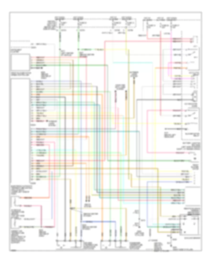
Automatic A/C Wiring Diagram, Early Production (1 of 2) for Ford Explorer 2002


List of elements for Automatic A/C Wiring Diagram, Early Production (1 of 2) for Ford Explorer 2002:
- A/c clutch relay
- A/c indicator diode
- Ambient air temperature sensor (right front of engine compt, near radiator support)
- Battery junction box (bjb) (left side of engine compt, at fender apron)
- Blower motor relay
- C201b
- C220a
- C228a
- C228b
- C270a
- C270b
- C270h
- Central junction box (cjb) (behind left side of dash)
- Computer data lines system
- Dash)
- Drivers temperature blend door actuator
- Electronic automatic temperature control module (eatc) (under left side of dash)
- Exterior lamps system
- Front blower motor
- Front blower motor speed controller
- Fuse 10 10a
- Fuse 15 5a
- Fuse 30 5a
- Fuse 36 40a
- Fuse 37 15a
- Fuse 7 15a
- G101 (behind left headlamp)
- G206 (behind center of dash)
- G300 (left side "a" pillar)
- Generic electric module (gem) (behind right side of dash)
- Generic electronic module (gem) (behind right side of dash)
- Hot at all times
- Hot in run and start
- In-vehicle temperature sensor (top left side of dash)
- Instrument cluster
- Interior lamps system
- J/c 1
- J/c 2
- Passenger temperature blend door actuator
- Remote solenoid assembly (behind right side of dash)
- S219
- S230
- S242 (behind center of dash)
- S243 (behind center of dash)
- S247 (behind center of dash)
- S317 (left center of vehicle)
- Seats system
- Sunload sensor
- Tan
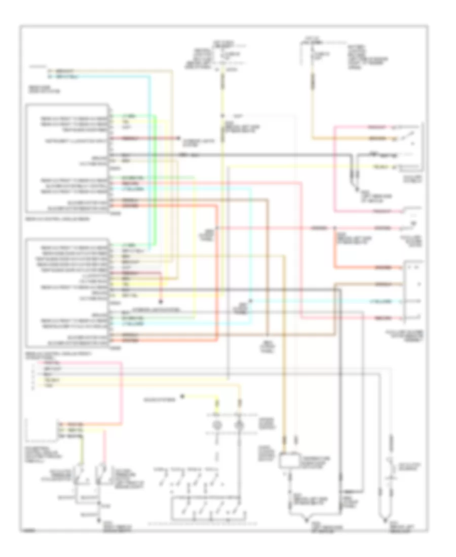
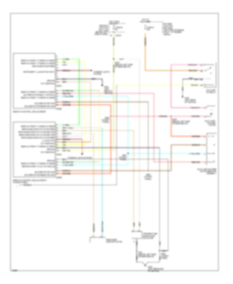
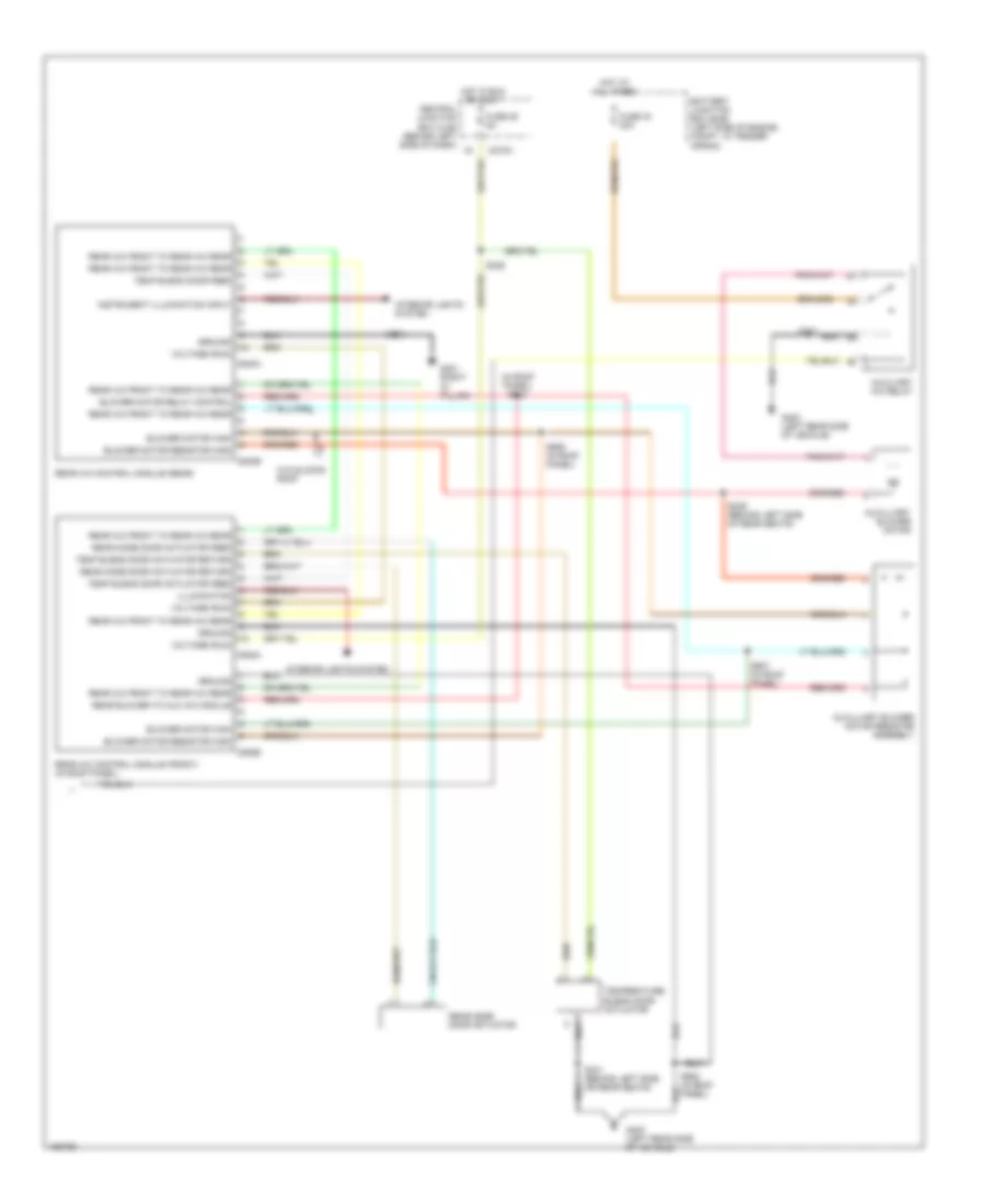
Automatic A/C Wiring Diagram, Early Production (2 of 2) for Ford Explorer 2002
List of elements for Automatic A/C Wiring Diagram, Early Production (2 of 2) for Ford Explorer 2002:
- A/c clutch pressure cycling swtch
- A/c clutch solenoid
- A/c high pressure switch (left front of engine compt)
- Air bag sliding contact
- Audio/ climate control switch
- Auxiliary a/c relay
- Auxilliary blower motor
- Auxilliary blower motor resistor assembly
- Battery junction box (bjb) (left side of engine compt, at fender apron)
- Blower motor high
- Blower motor relay control
- Blower motor resistor high
- C270a
- C938a
- C938b
- C940a
- C940b
- Central junction box (cjb) (behind left side of dash)
- Fuse 25 5a
- Fuse 33 30a
- G101 (behind left headlamp)
- G104 (right rear of engine compt)
- G403 (left rear side of vehicle)
- Ground
- Hot at all times
- Hot in run or accy
- Illumination
- Instrument illumination input
- Interior lights system
- Powertrain control module (mounted through firewall)
- Rear a/c control module (front) (in roof panel)
- Rear a/c control module (rear)
- Rear a/c front to rear a/c rear
- Rear blower to aux a/c module
- Rear mode door actuator
- Rear mode door actuator feed
- Rear mode door actuator return
- S135
- S339 (behind left side of rear seats)
- S341
- S341 (behind left side or rear seats)
- S905 (in roof panel)
- S906 (in roof panel)
- S907 (in roof panel)
- S908
- S908 (in roof panel)
- Sound systems
- Tan
- Temp blend door actuator feed
- Temp blend door actuator return
- Temp blend door feed
- Temperature blend door actuator
- Voltage (run)
Automatic A/C Wiring Diagram, Late Production (1 of 2) for Ford Explorer 2002
List of elements for Automatic A/C Wiring Diagram, Late Production (1 of 2) for Ford Explorer 2002:
- (behind center of dash)
- A/c clutch relay
- A/c indicator diode
- Ambient air temperature sensor (right front of engine compt, near radiator support)
- Battery junction box (bjb) (left side of engine compt, at fender apron)
- Blower motor relay
- C220a
- C228a
- C228b
- C270a
- C270b
- C270e
- C270h
- C3008e
- Central junction box (cjb) (behind left side of dash)
- Central security module (base of right "c" pillar)
- Computer data lines system
- Drivers temperature blend door actuator
- Electronic automatic temperature control module (eatc) (under left side of dash)
- Exterior lamps system
- Front blower motor
- Front blower motor speed controller
- Fuse 10 10a
- Fuse 15 5a
- Fuse 20 5a
- Fuse 30 5a
- Fuse 36 40a
- Fuse 37 15a
- Fuse 7 15a
- G101 (behind left headlamp)
- G200 (right side "a" pillar)
- G206 (behind center of dash)
- G300 (left side "a" pillar)
- Hot at all times
- Hot in run and start
- In-vehicle temperature sensor (top left side of dash)
- Instrument cluster
- Interior lamps system
- J/c 1
- J/c 2
- Passenger temperature blend door actuator
- Remote solenoid assembly (behind right side of dash)
- S219
- S229
- S233 (behind center of dash)
- S242 (behind center of dash)
- S243
- S247 (behind center of dash)
- S317 (left center of vehicle)
- Seats system
- Sunload sensor
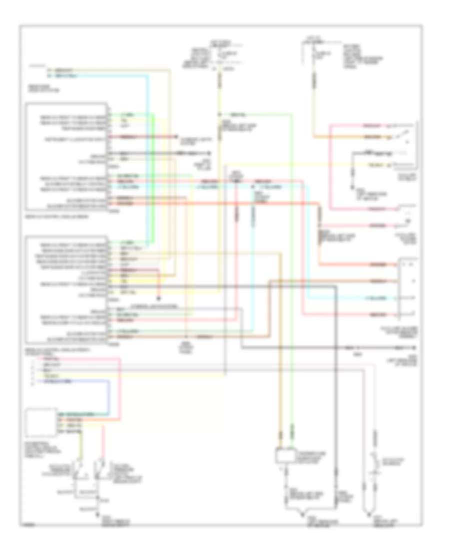
Automatic A/C Wiring Diagram, Late Production (2 of 2) for Ford Explorer 2002
List of elements for Automatic A/C Wiring Diagram, Late Production (2 of 2) for Ford Explorer 2002:
- A/c clutch pressure cycling siitch
- A/c clutch solenoid
- A/c high pressure switch (left front of engine compt)
- Auxiliary a/c relay
- Auxilliary blower motor
- Auxilliary blower motor resistor assembly
- Battery junction box (bjb) (left side of engine compt, at fender apron)
- Blower motor high
- Blower motor relay control
- Blower motor resistor high
- C270a
- C938a
- C938b
- C940a
- C940b
- Central junction box (cjb) (behind left side of dash)
- Fuse 25 5a
- Fuse 33 30a
- G101 (behind left headlamp)
- G104 (right rear of engine compt)
- G400 (left rear side of vehicle)
- G401 (right "d" pillar)
- G403 (left rear side of vehicle)
- Ground
- Hot at all times
- Hot in run or accy
- Illumination
- Instrument illumination input
- Interior lights system
- Powertrain control module (mounted through firewall)
- Rear a/c control module (front) (in roof panel)
- Rear a/c control module (rear)
- Rear a/c front to rear a/c rear
- Rear blower to aux a/c module
- Rear mode door actuator
- Rear mode door actuator feed
- Rear mode door actuator return
- S135
- S341
- S341 (behind left side or rear seats)
- S903
- S906 (in roof panel)
- S907 (in roof panel)
- S908
- S908 (in roof panel)
- S910 (in roof panel)
- Temp blend door actuator feed
- Temp blend door actuator return
- Temp blend door feed
- Temperature blend door actuator
- Voltage (run)
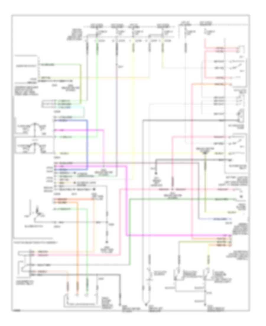
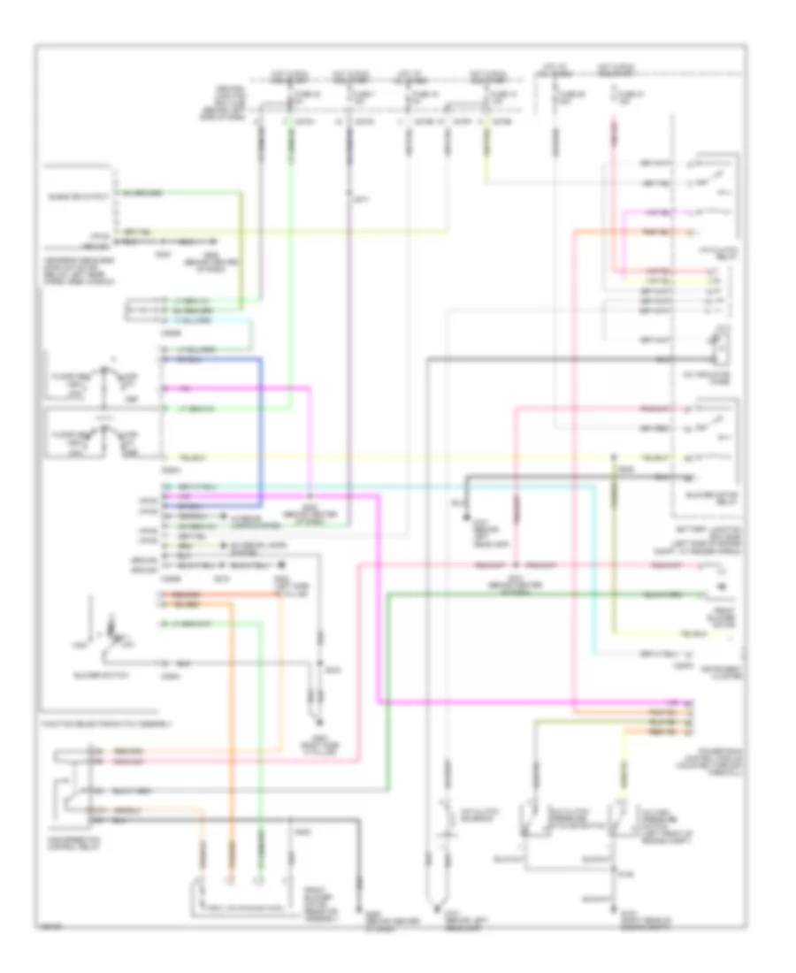
Manual A/C Wiring Diagram, Early Production (1 of 2) for Ford Explorer 2002
List of elements for Manual A/C Wiring Diagram, Early Production (1 of 2) for Ford Explorer 2002:
- (behind center of dash) s249
- 87a
- A/c clutch pressure cycling switch
- A/c clutch relay
- A/c clutch solenoid
- A/c high pressure switch (left front of engine compt)
- A/c indicator diode
- Battery junction box (bjb) (left side of engine compt, at fender apron)
- Blend dr output
- Blower motor relay
- Blower switch
- C201b
- C270a
- C270b
- C270e
- C270f
- C270h
- C294a
- C294b
- C294c
- Central junction box (cjb) (behind left side of dash)
- Def
- Exterior lamps system
- Floor
- Floor/vent
- Front blower motor
- Front blower motor resistor assembly
- Function selector switch assembly
- Fuse 10 10a
- Fuse 16 15a
- Fuse 30 5a
- Fuse 36 40a
- Fuse 37 15a
- Fuse 7 15a
- G101 (behind left headlamp)
- G104 (right rear of engine compt)
- G200 (right side "a" pillar)
- G206 (behind center of dash)
- G300 (left side "a" pillar)
- Gereric electronic module (gem) (behind right side of dash)
- Ground
- High
- High speed fan control relay
- Hot at all times
- Hot in run and start
- Interior lamps system
- J/c 1
- J/c 2
- Low
- Max
- Med 1 med 2
- Mix
- Off
- Powertrain control module (mounted through firewall)
- S135
- S219
- S222 (behind center of dash)
- S229
- S240
- S241 (behind center of dash)
- S317
- Temperature blend door actuator (below left rear cargo area window)
- Vent
- Vpwr
Manual A/C Wiring Diagram, Early Production (2 of 2) for Ford Explorer 2002
List of elements for Manual A/C Wiring Diagram, Early Production (2 of 2) for Ford Explorer 2002:
- Auxiliary a/c relay
- Auxilliary blower motor
- Auxilliary blower motor resistor assembly
- Battery junction box (bjb) (left side of engine compt, at fender apron)
- Blower motor high
- Blower motor relay control
- Blower motor resistor high
- C270a
- C938a
- C938b
- C940a
- C940b
- Central junction box (cjb) (behind left side of dash)
- Fuse 25 5a
- Fuse 33 30a
- G403 (left rear of vehicle)
- G403 (left rear side of vehicle)
- Ground
- Hot at all times
- Hot in run or accy
- Illumination
- Instrument illumination input
- Interior lights system
- Rear a/c control module (front) (in roof panel)
- Rear a/c control module (rear)
- Rear a/c front to rear a/c rear
- Rear blower to aux a/c module
- Rear mode door actuator
- Rear mode door actuator feed
- Rear mode door actuator return
- S339 (behind left side of rear seats)
- S341
- S341 (behind left side or rear seats)
- S905 (in roof panel)
- S906 (in roof panel)
- S907 (in roof panel)
- S908
- S908 (in roof panel)
- Temp blend door actuator feed
- Temp blend door actuator return
- Temp blend door feed
- Temperature blend door actuator
- Voltage (run)
Manual A/C Wiring Diagram, Late Production (1 of 2) for Ford Explorer 2002
List of elements for Manual A/C Wiring Diagram, Late Production (1 of 2) for Ford Explorer 2002:
- 87a
- A/c clutch pressure cycling switch
- A/c clutch relay
- A/c clutch solenoid
- A/c high pressure switch (left front of engine compt)
- A/c indicator diode
- Battery junction box (bjb) (left side of engine compt, at fender apron)
- Blend dr output
- Blower motor relay
- Blower switch
- C220a
- C270a
- C270b
- C270e
- C270f
- C270h
- C294a
- C294b
- C294c
- Central junction box (cjb) (behind left side of dash)
- Def
- Exterior lamps system
- Floor
- Floor/vent
- Front blower motor
- Front blower motor resistor assembly
- Function selector switch assembly
- Fuse 10 10a
- Fuse 16 5a
- Fuse 30 5a
- Fuse 36 40a
- Fuse 37 15a
- Fuse 7 15a
- G101 (behind left headlamp)
- G104 (right rear of engine compt)
- G200 (right side "a" pillar)
- G206 (behind center of dash)
- G300 (left side "a" pillar)
- Ground
- High
- High speed fan control relay
- Hot at all times
- Hot in run and start
- Instrument cluster
- Interior lamps system
- J/c 2
- Low
- Max
- Med 1 med 2
- Mix
- Off
- Powertrain control module (mounted through firewall)
- S135
- S216
- S219
- S222 (behind center of dash)
- S240
- S241 (behind center of dash)
- S249
- S317
- Temperature blend door actuator (below left rear cargo area window)
- Vent
- Vpwr
Manual A/C Wiring Diagram, Late Production (2 of 2) for Ford Explorer 2002
List of elements for Manual A/C Wiring Diagram, Late Production (2 of 2) for Ford Explorer 2002:
- (in roof panel)
- Auxiliary a/c relay
- Auxilliary blower motor
- Auxilliary blower motor resistor assembly
- Battery junction box (bjb) (left side of engine compt, at fender apron)
- Blower motor high
- Blower motor relay control
- Blower motor resistor high
- C270a
- C938a
- C938b
- C940a
- C940b
- Central junction box (cjb) (behind left side of dash)
- Fuse 25 5a
- Fuse 33 30a
- G400 (left rear side of vehicle)
- G401 (right "d" pillar)
- G403 (left rear side of vehicle)
- Ground
- Hot at all times
- Hot in run or accy
- Illumination
- Instrument illumination input
- Interior lights system
- Rear a/c control module (front) (in roof panel)
- Rear a/c control module (rear)
- Rear a/c front to rear a/c rear
- Rear blower to aux a/c module
- Rear mode door actuator
- Rear mode door actuator feed
- Rear mode door actuator return
- S326
- S339 (behind left side of rear seats)
- S341
- S341 (behind left side or rear seats)
- S903
- S906 (in roof panel)
- S907 (in roof panel)
- S908 (in roof panel)
- S910
- Temp blend door actuator feed
- Temp blend door actuator return
- Temp blend door feed
- Temperature blend door actuator
- Voltage (run)
- W/o sliding roof

 English