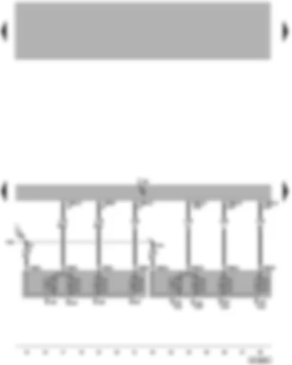
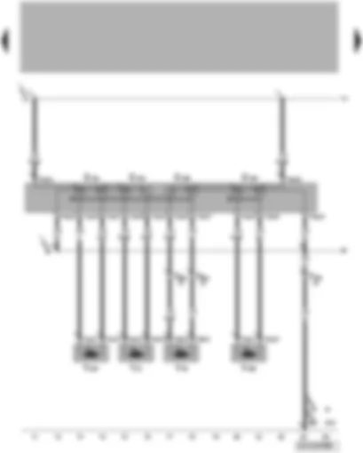
Wiring Diagram VW PASSAT 2005 - Control unit for seat adjustment and steering column adjustment with memory function - driver seat adjustment operating unit

| E335 | Lumbar support height adjustment button |
| E336 | Lumbar support longitudinal adjustment button |
| E418 | Seat longitudinal adjustment button |
| E425 | Backrest adjustment button |
| E451 | Seat front height adjustment button |
| E452 | Seat rear height adjustment button |
| J136 | Seat and steering column adjustment control unit with memory |
| S224 | Fuse in fuse holder on left under dash panel |
| T4br | 4-pin connector, black |
| T6bn | 6-pin connector, blue |
| T10aa | 10-pin connector |
| T10c | 10-pin connector, black, coupling point driver side, under seat |
| T26b | 26-pin connector, white |
| 77 | Earth point, lower part of left B-pillar |
| M95 | Connection 3, seat adjustment wiring harness |
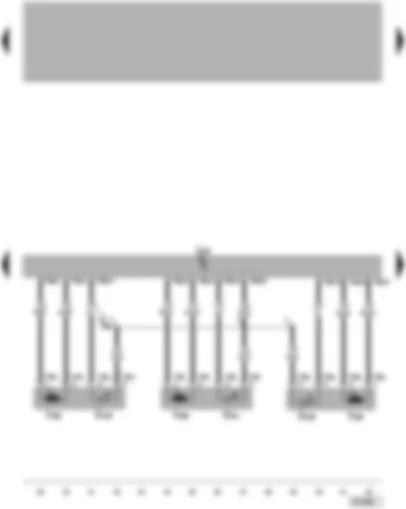
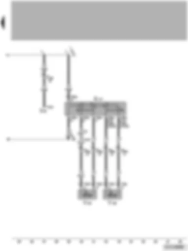
Wiring Diagram VW PASSAT 2005 - Seat and steering column adjustment control unit with memory - seat memory position button 1-3
| E218 | Seat memory position button 1 |
| E219 | Seat memory position button 2 |
| E220 | Seat memory position button 3 |
| E337 | Massage function button |
| E447 | Seat position memory button |
| J136 | Seat and steering column adjustment control unit with memory |
| T6bl | 6-pin connector, black |
| T6bk | 6-pin connector, black |
| T26b | 26-pin connector, white |
| M95 | Connection 3, seat adjustment wiring harness |
| * | Only seats with no massage function |
| ** | Only seats with massage function |
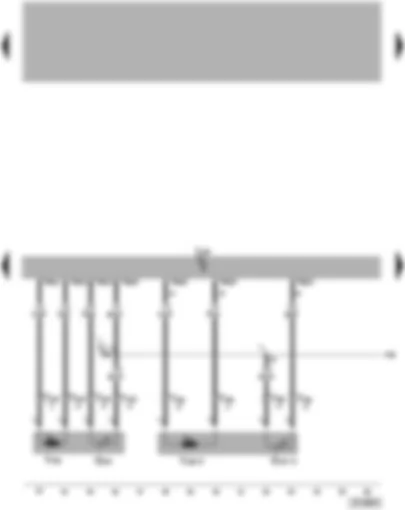
Wiring Diagram VW PASSAT 2005 - Seat and steering column adjustment control unit with memory - seat height adjustment sender
| G438 | Seat front height adjustment sender |
| G439 | Seat rear height adjustment sender |
| G441 | Seat longitudinal adjustment sender |
| J136 | Seat and steering column adjustment control unit with memory |
| T4bs | 4-pin connector, black |
| T4bt | 4-pin connector, black |
| T4bw | 4-pin connector, black |
| T6bh | 6-pin connector, brown |
| T6bi | 6-pin connector, blue |
| T6bj | 6-pin connector, black |
| V285 | Seat rear height adjustment motor |
| V288 | Seat longitudinal adjustment motor |
| V296 | Seat front height adjustment motor |
| M94 | Connection 2, seat adjustment wiring harness |
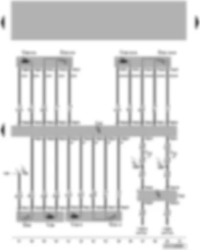
Wiring Diagram VW PASSAT 2005 - Seat and steering column adjustment control unit with memory - lumbar support adjustment operating unit
| G374 | Lumbar support height adjustment sender |
| G375 | Lumbar support longitudinal adjustment sender |
| J136 | Seat and steering column adjustment control unit with memory |
| T4cd | 4-pin connector, black |
| T4dz | 4-pin connector, black |
| T6bp | 6-pin connector, blue |
| T6bq | 6-pin connector, white |
| V229 | Lumbar support height adjustment motor |
| V230 | Lumbar support longitudinal adjustment motor |
| M96 | Connection 4, seat adjustment wiring harness |
| * | Only seats with no massage function |
Wiring Diagram VW PASSAT 2005 - Seat and steering column adjustment control unit with memory - data bus diagnostic interface - self-diagnosis connection
| G423 | Potentiometer for height adjustment of lumbar support with massage function |
| G440 | Backrest adjustment sender |
| J136 | Seat and steering column adjustment control unit with memory |
| J533 | Data bus diagnosis interface |
| T2gb | 2-pin connector, black, in seat |
| T3cp | 3-pin connector, black, in seat |
| T4br | 4-pin connector, black |
| T4bx | 4-pin connector, black |
| T4nk | 4-pin connector, black, in seat |
| T4nl | 4-pin connector, black, in seat |
| T6bp | 6-pin connector, blue |
| T6bq | 6-pin connector, white |
| T8ae | 8-pin connector, black, in seat |
| T10c | 10-pin connector, black, coupling point driver side, under seat |
| T16d | 16-pin connector, self-diagnosis connection |
| T20e | 20-pin connector |
| V286 | Backrest adjustment motor |
| V328 | Lumbar support massage function pump |
| B397 | Connection 1 (convenience CAN bus, high), in main wiring harness |
| B406 | Connection 1 (convenience CAN bus, low), in main wiring harness |
| M96 | Connection 4, seat adjustment wiring harness |
| * | Only seat with massage function, applicable to April 2005 |
| ** | Only seat with massage function, applicable from May 2005 to April 2006 |
| *** | Only seat with massage function, applicable from May 2006 |
Wiring Diagram VW PASSAT 2005 - Longitudinal adjustment for front passenger seat - height adjustment for front passenger seat - backrest adjustment for front passenger seat - tilt angle adjustment
| E418 | Seat longitudinal adjustment button |
| E421 | Rake adjustment button |
| E424 | Seat height adjustment button |
| E425 | Backrest adjustment button |
| T2dx | 2-pin connector |
| T4ce | 4-pin connector |
| T4cr | 4-pin connector |
| T4cs | 4-pin connector |
| T4nm | 4-pin connector, black |
| T6bo | 6-pin connector |
| T10d | 10-pin connector, black, coupling point front passenger side, under seat |
| T10z | 10-pin connector |
| V31 | Front passenger seat longitudinal adjustment motor |
| V46 | Front passenger seat backrest adjustment motor |
| V244 | Front passenger seat rake adjustment motor |
| V246 | Front passenger seat height adjustment motor |
| 78 | Earth point, lower part of right B-pillar |
| 95 | Earth connection 1, in seat adjustment wiring harness |
| 683 | Earth point on front of right side member |
| M1 | Positive connection 1 (30), in seat adjustment wiring harness |
| * | Applicable to April 2005 |
| ** | Valid from May 2005 |
Wiring Diagram VW PASSAT 2005 - Front passenger seat lumbar support adjustment switch
| E177 | Front passenger seat lumbar support adjustment switch |
| S46 | Front passenger seat adjustment thermal fuse 1 |
| T2r | 2-pin connector |
| T2dy | 2-pin connector |
| T2dz | 2-pin connector |
| T6bm | 6-pin connector |
| T6bo | 6-pin connector |
| T10d | 10-pin connector, black, coupling point front passenger side, under seat |
| V126 | Front passenger seat lumbar support longitudinal adjustment motor |
| V130 | Front passenger seat lumbar support height adjustment motor |
| 95 | Earth connection 1, in seat adjustment wiring harness |
| M1 | Positive connection 1 (30), in seat adjustment wiring harness |
| * | Applicable to April 2005 |
| ** | Valid from May 2005 |
VW PASSAT 2005
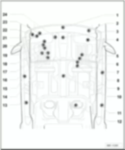
VW PASSAT 2005 Overview of control units
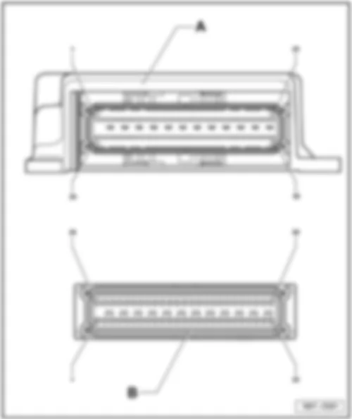
| 1 - | Airbag control unit -J234- |
| q | Fitting location → Chapter |
| q | 50-pin connector assignment ⇒ applicable to October 2007 → Chapter |
| q | 50-pin connector assignment ⇒ applicable to October 2007 |
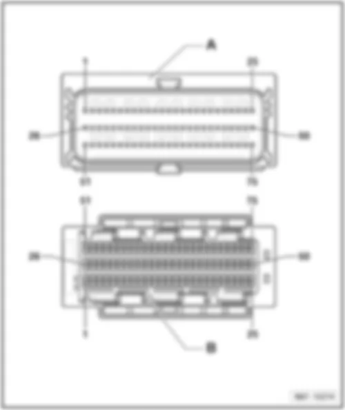
| q | 75-pin connector assignment ⇒ applicable to October 2007 → Chapter |
| q | 75-pin connector assignment ⇒ applicable to October 2007 |
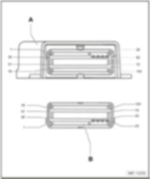
| q | 100-pin connector assignment ⇒ applicable from November 2007 → Chapter |
| q | 100-pin connector assignment ⇒ applicable from November 2007 |
| 2 - | Convenience system central control unit -J393- |
| q | Fitting location → Chapter |
| q | Connector assignment → Chapter |
| q | Connections → Chapter |
| 3 - | Air conditioning system control unit -J301- / Climatronic control unit -J255- |
| q | Air conditioning system control unit -J301- → Chapter |
| q | Connector assignment → Chapter |
| q | Connections → Anchor |
| q | Climatronic control unit -J255- → Chapter |
| q | Connector assignment → Chapter |
| q | Connections → Anchor |
| 4 - | Cornering light and headlight range control unit -J745- |
| q | Fitting location → Chapter |
| 5 - | Heated rear seats control unit -J786- |
| q | Fitting location → Chapter |
| 6 - | Seat occupied recognition control unit -J706- |
| q | Fitting location → Chapter |
| q | Connector assignment → Chapter |
| q | Connections → Anchor |
| 7 - | Aerial selection control unit -J515- |
| q | Fitting location → Chapter |
| 8 - | Front passenger door control unit -J387- |
| q | Fitting location → Chapter |
| q | Connector assignment → Chapter |
| q | Connections → Anchor |
| 9 - | Mobile telephone operating electronics control unit -J412- / Telephone controls control unit -J738- |
| q | Fitting location → Chapter |
| q | Connector assignment → Chapter |
| q | Connections → Anchor |
| 10 - | Control unit for electromechanical parking brake -J540- |
| q | Fitting location → Chapter |
| q | Connector assignment → Chapter |
| q | Connections → Anchor |
| 11 - | Rear right door control unit -J389- |
| q | Fitting location → Chapter |
| q | Connector assignment → Chapter |
| q | Connections → Anchor |
| 12 - | Fuel pump control unit -J538- |
| q | Fitting location → Chapter |
| q | Connector assignment → Chapter |
| q | Connections → Anchor |
| 13 - | Rear left door control unit -J388- |
| q | Fitting location → Chapter |
| q | Connector assignment → Chapter |
| q | Connections → Anchor |
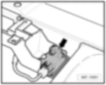
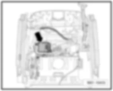
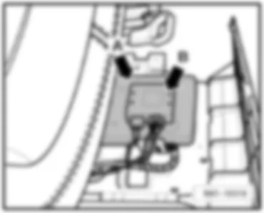
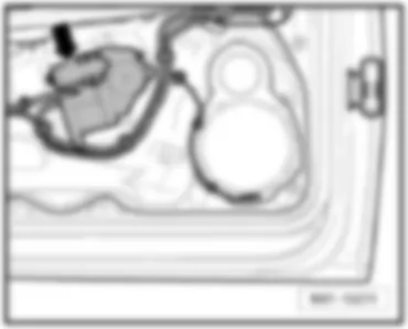
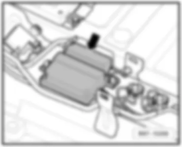
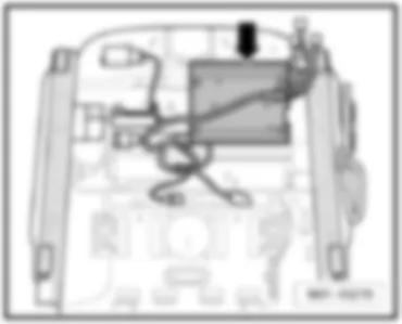
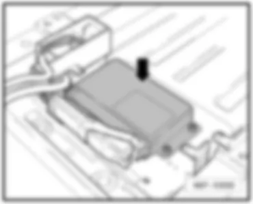
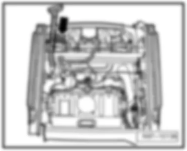
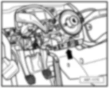
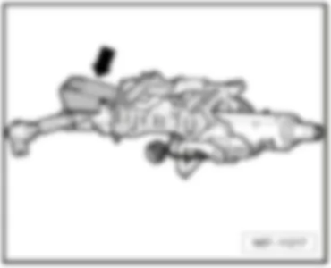
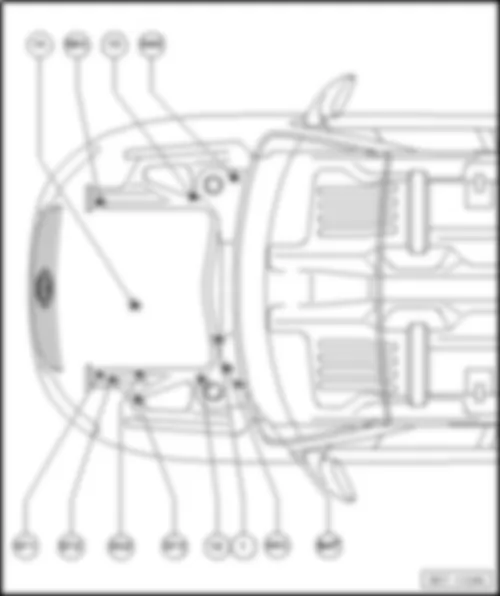
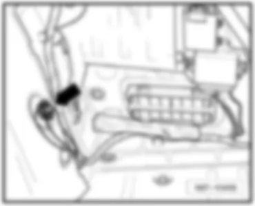
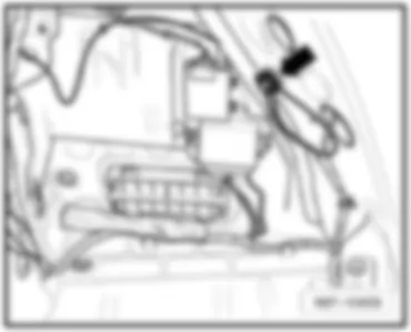
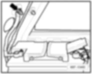
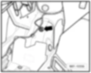
| 14 - | Seat and steering column adjustment control unit with memory -J136- |
| q | Fitting location → Chapter |
| q | Connector assignment → Chapter |
| q | Connections → Chapter |
| 15 - | Driver door control unit -J386- |
| q | Fitting location → Chapter |
| q | Connector assignment → Chapter |
| q | Connections → Anchor |
| 16 - | Special vehicle control unit -J608- |
| q | Fitting location → Chapter |
| 17 - | Heated front seats control unit -J774- |
| q | Fitting location → Chapter |
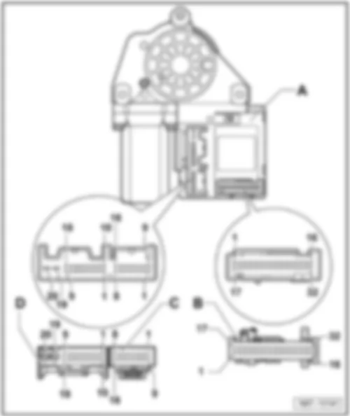
| 18 - | Steering column electronics control unit -J527- |
| q | Fitting location → Chapter |
| q | Connector assignment → Chapter |
| q | B - Connector cruise control system (CCS) and turn signal → Item |
| q | C - 20-pin connector -T20d- → Item |
| q | D - 4-pin connector -T4- → Anchor |
| q | E - Connector for wiper and multifunction display → Item |
| q | F - Connector for steering angle sensor → Anchor |
| q | G - Connector for airbag return spring/multifunction steering wheel → Anchor |
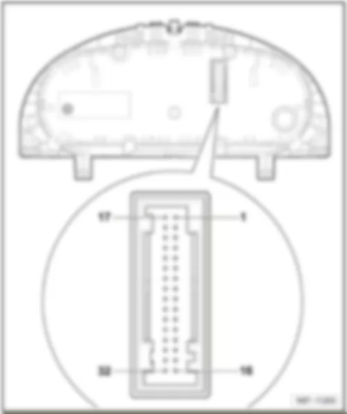
| 19 - | Dash panel insert -K- / Control unit in dash panel insert -J285- |
| q | 36-pin connector -T36- → Chapter ⇒ applicable to October 2008 |
| q | 32-pin connector -T32c- → Chapter ⇒ applicable from November 2008 |
| 20 - | Electronic steering column lock control unit -J764- |
| q | Fitting location → Chapter |
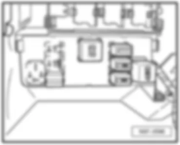
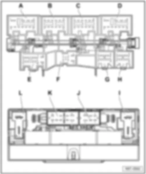
| 21 - | Onboard supply control unit -J519- |
| q | Fitting location → Chapter |
| q | A - 11-pin connector -T11- → Chapter |
| q | B - 12-pin connector -T12i- → Item |
| q | C - 12-pin connector -T12k- → Item |
| q | D - 11-pin connector -T11a- → Item |
| q | E - 16-pin connector -T16g- → Chapter |
| q | F- 8-pin connector -T8t- → Chapter |
| q | G - 12-pin connector -T12m- - → Anchor |
| q | H- 12-pin connector -T12- → Anchor |
| q | I - 2-pin connector -T2cp- → Anchor |
| q | J - 6-pin connector -T6ap- → Item |
| q | K - 10-pin connector -T10s- → Anchor |
| q | L - 2-pin connector -T2cq- → Anchor |
| 22 - | Driving school mode relay -J746- / Taxi alarm remote control control unit -J601- |
| q | Fitting location → Chapter |
| q | Connections → Chapter |
| 23 - | Park assist steering control unit -J791- / Parking aid control unit -J446- |
| q | Fitting location ⇒ → Chapter |
| 24 - | Data bus diagnostic interface -J533- |
| q | Fitting location → Chapter |
| q | Connector assignment → Chapter |
| q | Connections → Anchor |
|
|
| 50-pin connector: |
| A - | Airbag control unit -J234- |
| Pin connector: |
| B - | 50-pin connector -T50- |
Note
| applicable to October 2007 |
| 75-pin connector: |
| A - | Airbag control unit -J234- |
| Pin connector: |
| B - | 75-pin connector -T75- |
Note
| applicable to October 2007 |
| 100-pin connector: |
| A - | Airbag control unit -J234- |
| Pin connector: |
| B - | 100-pin connector -T100- |
| B - | 100-pin connector -T100a- |
Note
| applicable from November 2007 |
|
| Connector assignment: |
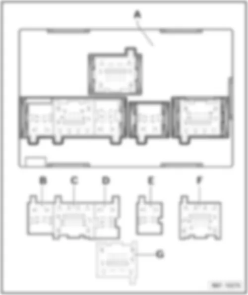
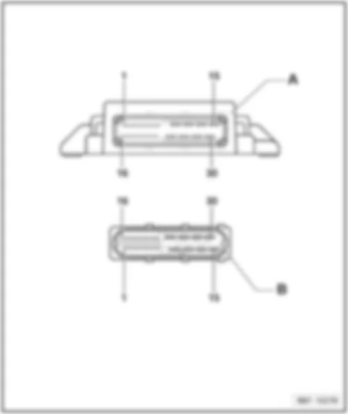
| A - | Convenience system central control unit -J393- |
| Pin connector: |
| B - | 6-pin connector -T6an- |
| C - | 18-pin connector -T18a- |
| D - | 8-pin connector -T8r- |
| E - | 6-pin connector -T6ao- |
| F - | 18-pin connector -T18b- |
| G - | 18-pin connector -T18c- |
Note
| 18-pin connector -T18c- Discontinued on models with no entry and start authorisation |
| Air conditioning system control unit -J301- |
| Connector assignment: |
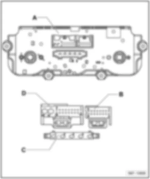
| A - | Air conditioning system control unit -J301- |
| Connector: |
| B - | 16-pin connector -T16j- |
| C - | 5-pin connector -T5r- |
| D - | 20-pin connector -T20b- |
| Climatronic control unit -J255- |
| Connector assignment: |
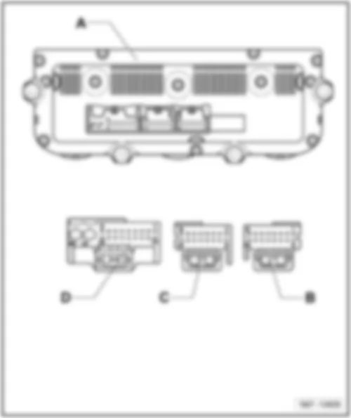
| A - | Climatronic control unit -J255- |
| Connector: |
| B - | 16-pin connector -T16h- |
| C - | 16-pin connector -T16i- |
| D - | 20-pin connector -T20c- |
|
|
|
| Connector assignment: |
| A - | Seat occupied recognition control unit -J706- |
| Connector: |
| B - | 18-pin connector -T18f- |
Note:
|
| Connector assignment: |
| A - | Front passenger door control unit -J387- , Driver door control unit -J386- |
| Connector: |
| B - | 32-pin connector -T32a- , -32-pin connector -T32b- |
| C - | 16-pin connector -T16a- -, -16-pin connector -T16b- |
| D - | 20-pin connector -T20g- , -20-pin connector -T20h- |
|
| Connector assignment: |
| A - | Mobile telephone operating electronics control unit -J412- |
| Connector: |
| B - | 54-pin connector -T54- |
|
| Connector assignment: |
| A - | Control unit for electromechanical parking brake -J540- |
| Connector: |
| B - | 30-pin connector -T30- |
Note:
|
| Connector assignment: |
| A - | Rear right door control unit -J389- , Rear left door control unit -J388- |
| Connector: |
| B - | 18-pin connector -T18- |
|
| Connector assignment: |
| A - | Fuel pump control unit -J538- |
| Connector: |
| B - | 10-pin connector -T10p- |
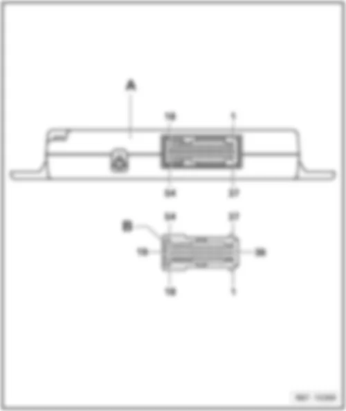
|
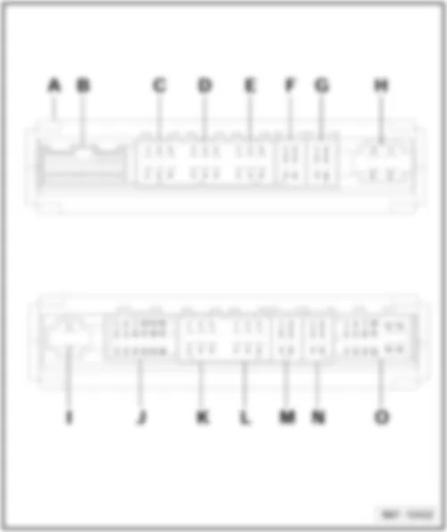
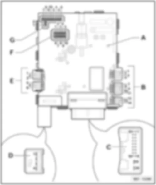
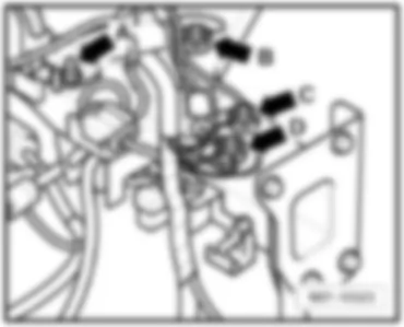
| Connector assignment: |
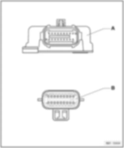
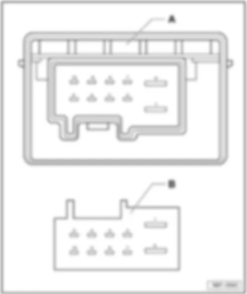
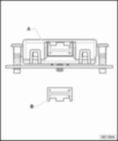
| A - | Seat and steering column adjustment control unit with memory -J136- |
| Pin connector: |
| B - | 26-pin connector -T26b- |
| C - | 6-pin connector -T6bj- |
| D - | 6-pin connector -T6bq- |
| E - | 6-pin connector -T6bi- |
| F - | 6-pin connector -T6bh- |
| G - | 6-pin connector -T6bp- |
| H - | 4-pin connector -T4br- |
| I - | 2-pin connector -T2- , Not assigned |
| J - | 2-pin connector -T2- , Not assigned |
| K - | 6-pin connector -T6- , Not assigned |
| L - | 6-pin connector -T6- , Not assigned |
| M - | 6-pin connector -T6- , Not assigned |
| N - | 6-pin connector -T6- , Not assigned |
| O - | 16-pin connector -T16- , Not assigned |
|
|
|
| Connector assignment: |
| A - | Steering column electronics control unit -J527- |
| B - | Cruise control system (CCS) and turn signal connector: |
| 1 - | Turn signal earth |
| 2 - | Turn signal |
| 3 - | Not assigned |
| 4 - | Main beam/flasher |
| 5 - | Not assigned |
| 6 - | Not assigned |
| 7 - | Voltage for CCS off |
| 8 - | CCS master switch |
| 9 - | Res (+), Set (-) |
| 10 - | CCS off |
| 11 - | Earth for CCS |
| 12 - | Earth for automatic distance control |
| 13 - | Adaptive cruise control button |
| 14 - | Set switch |
| C - | 20-pin connector -T20d- |
| 1 - | Ignition key withdrawal lock |
| 2 - | Immobiliser reading unit |
| 3 - | Convenience CAN bus, low |
| 4 - | Convenience CAN bus, high |
| 5 - | Powertrain CAN, screening |
| 6 - | Powertrain CAN, low |
| 7 - | Powertrain CAN, high |
| 8 - | Earth |
| 9 - | Power supply to control unit for steering column electronics |
| 10 - | Terminal 50 |
| 11 - | Terminal P |
| 12 - | Terminal S |
| 13 - | Terminal 15 |
| 14 - | Not assigned |
| 15 - | Not assigned |
| 16 - | Cruise control system, out |
| 17 - | Earth |
| 18 - | Power supply to control unit for steering column electronics (terminal 30) |
| 19 - | Not assigned |
| 20 - | Not assigned |
| D - | 4-pin connector -T4- |
| 1 - | Airbag 1 - |
| 2 - | Airbag 1 + |
| 3 - | Airbag 2 + |
| 4 - | Airbag 2 - |
| E - | Connector for wiper and multifunction display: |
| 1 - | Earth for intermittent windscreen wiper switch |
| 2 - | Wiper signal |
| 3 - | Wash/wipe signal |
| 4 - | Potentiometer for intermittent stages |
| 5 - | Multifunction display signal |
| 6 - | Earth for multifunction display and interval |
| F - | Steering angle sensor connector: |
| 1 - | Photoelectric beam 5 |
| 2 - | Photoelectric beam 3 |
| 3 - | Photoelectric beam 1 |
| 4 - | 12 volt voltage supply |
| 5 - | 5 volt voltage supply |
| 6 - | Photoelectric beam 6 |
| 7 - | Photoelectric beam 4 |
| 8 - | Photoelectric beam 2 |
| 9 - | Earth |
| 10 - | Photoelectric beam 7 |
| G - | Connector for airbag return spring/multifunction steering wheel: |
| 1 - | Not assigned |
| 2 - | Not assigned |
| 3 - | Airbag 1 (+) |
| 4 - | Airbag 1 (-) |
| 5 - | Airbag 2 (+) |
| 6 - | Airbag 2 (-) |
| 7 - | Earth for return spring, multifunction steering wheel and horn |
| 8 - | Horn or CCS off (with multifunction steering wheel) |
| 9 - | LIN bus |
| 10 - | Power supply for multifunction steering wheel (terminal 15) |
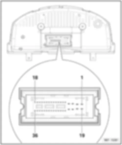
| Dash panel insert -K- / Control unit in dash panel insert -J285- |
| 36-pin connector -T36- : |
| 1 - | Terminal 15 voltage supply |
| 2 - | Terminal 30 voltage supply |
| 3 - | Not assigned |
| 4 - | Not assigned |
| 5 - | Brake fluid level warning lamp |
| 6 - | Warning lamp for electric parking brake and handbrake |
| 7 - | Not assigned |
| 8 - | Not assigned |
| 9 - | Not assigned |
| 10 - | Not assigned |
| 11 - | Not assigned |
| 12 - | Diagnostic interface for dash panel CAN data bus, low |
| 13 - | Diagnostic interface for dash panel CAN data bus, high |
| 14 - | Dash panel CAN screening |
| 15 - | Dash panel CAN wake-up wire |
| 16 - | Fuel gauge sender (full), only with all-wheel drive |
| 17 - | Fuel gauge sender (full) |
| 18 - | Fuel gauge sender (empty) |
| 19 - | Terminal 31 |
| 20 - | Not assigned |
| 21 - | Not assigned |
| 22 - | Front left brake pad wear sender |
| 23 - | Fuel gauge sender (empty), only with all-wheel drive |
| 24 - | Not assigned |
| 25 - | Oil pressure warning lamp |
| 26 - | Oil level and oil temperature sender |
| 27 - | Not assigned |
| 28 - | Speed signal, sliding sunroof adjustment control unit output, control unit with display for radio and navigation system |
| 29 - | Not assigned |
| 30 - | Not assigned |
| 31 - | Not assigned |
| 32 - | Not assigned |
| 33 - | Terminal 31, sensor earth |
| 34 - | Washer fluid level warning lamp |
| 35 - | Coolant temperature and coolant shortage warning lamp |
| 36 - | Ambient temperature sensor |
| Note
|
| 32-pin connector -T32c- |
| 1 - | Fuel gauge sender (full) |
| 2 - | Fuel gauge sender (empty) |
| 3 - | Fuel gauge sender (full), only with all-wheel drive |
| 4 - | Fuel gauge sender (empty), only with all-wheel drive |
| 5 - | Not assigned |
| 6 - | Not assigned |
| 7 - | Not assigned |
| 8 - | Not assigned |
| 9 - | Speed signal, sliding sunroof adjustment control unit output, control unit with display for radio and navigation system |
| 10 - | Not assigned |
| 11 - | Oil level and oil temperature sender |
| 12 - | Not assigned |
| 13 - | Not assigned |
| 14 - | Not assigned |
| 15 - | Front left brake pad wear sender |
| 16 - | Terminal 31 |
| 17 - | Washer fluid level warning lamp |
| 18 - | Coolant temperature and coolant shortage warning lamp |
| 19 - | Ambient temperature sensor |
| 20 - | Terminal 31, sensor earth |
| 21 - | Not assigned |
| 22 - | Not assigned |
| 23 - | Not assigned |
| 24 - | Not assigned |
| 25 - | Warning lamp for electric parking brake and handbrake |
| 26 - | Brake fluid level warning lamp |
| 27 - | Oil pressure warning lamp |
| 28 - | Diagnostic interface for dash panel CAN data bus, high |
| 29 - | Diagnostic interface for dash panel CAN data bus, low |
| 30 - | Not assigned |
| 31 - | Terminal 15 voltage supply |
| 32 - | Terminal 30 voltage supply |
| Note
|
|
|
| Connector assignment: |
| A - | 11-pin connector -T11- |
| 1 - | Terminal 30 |
| 2 - | Right dipped beam bulb |
| 3 - | Right main beam bulb |
| 4 - | Right fog light bulb |
| 5 - | Right gas discharge (xenon) bulb |
| 6 - | Front right turn signal bulb |
| 7 - | Left side light bulb |
| 8 - | Not assigned |
| 9 - | Earth |
| 10 - | Electric fuel pump 2 relay |
| 11 - | Terminal 50 voltage supply relay |
| B - | 12-pin connector -T12i- |
| 1 - | Right reversing light bulb |
| 2 - | Heated windscreen relay |
| 3 - | Not assigned |
| 4 - | Rear left fog light bulb |
| 5 - | Right brake and tail light bulb |
| 6 - | Not assigned |
| 7 - | Front left entry light, front right entry light |
| 8 - | Not assigned |
| 9 - | Right tail light bulb (side light) |
| 10 - | Rear right turn signal bulb |
| 11 - | Front interior light |
| 12 - | Terminal 58d |
| C - | 12-pin connector -T12k- |
| 1 - | Heated driver seat control unit, heated front passenger seat control unit |
| 2 - | Left brake light bulb |
| 3 - | Right fog light bulb (right-hand drive only) |
| 4 - | Not assigned |
| 5 - | Not assigned |
| 6 - | Not assigned |
| 7 - | Not assigned |
| 8 - | Registration plate left light, number plate right light |
| 9 - | High level brake light bulb |
| 10 - | Left tail light bulb (side light) |
| 11 - | Rear left turn signal bulb |
| 12 - | Left reversing light bulb (right-hand drive only) |
| D - | 11-pin connector -T11a- |
| 1 - | Terminal 30 |
| 2 - | Left fog light bulb |
| 3 - | Left headlight main beam bulb |
| 4 - | Left headlight dipped beam bulb |
| 5 - | Earth |
| 6 - | Left gas discharge (xenon) bulb |
| 7 - | Terminal 15 voltage supply relay |
| 8 - | Headlight washer system relay |
| 9 - | Not assigned |
| 10 - | Right side light bulb |
| 11 - | Front left turn signal bulb |
| Connector assignment: |
| E - | 16-pin connector -T16g- |
| 1 - | Lighting switch terminal 58 |
| 2 - | Brake light switch |
| 3 - | Not assigned |
| 4 - | Not assigned |
| 5 - | Not assigned |
| 6 - | Fog light switch |
| 7 - | Earth (for manual gearbox only), mechatronics for dual clutch gearbox, multifunction switch (for automatic gearbox only) |
| 8 - | Lighting switch terminal 56 |
| 9 - | Not assigned |
| 10 - | Not assigned |
| 11 - | Not assigned |
| 12 - | Not assigned |
| 13 - | Light switch (rear fog light) |
| 14 - | Light switch (assistance light) |
| 15 - | Not assigned |
| 16 - | Light switch (day driving light) |
| F - | 8-pin connector -T8t- |
| 1 - | Terminal 50 voltage supply relay |
| 2 - | Terminal 15 voltage supply relay |
| 3 - | Windscreen wiper motor, rain and light detector sensor (LIN bus) |
| 4 - | Alternator |
| 5 - | Bonnet contact switch |
| 6 - | Reversing light switch |
| 7 - | Terminal 30 |
| 8 - | Terminal 31 |
| G - | 12-pin connector -T12m- |
| 1 - | Steering column electronics control unit terminal 50 |
| 2 - | Indicator lamp for hazard warning light |
| 3 - | Not assigned |
| 4 - | Illumination regulators, switches, instruments |
| 5 - | Not assigned |
| 6 - | Not assigned |
| 7 - | Convenience CAN bus, low |
| 8 - | Convenience CAN bus, high |
| 9 - | Hazard warning light switch |
| 10 - | Illumination regulators, switches, instruments |
| 11 - | Steering column electronics control unit terminal 15 |
| 12 - | Illumination regulators, switches, instruments |
| H - | 12-pin connector -T12- |
| t | Not assigned |
| I - | 2-pin connector -T2cp- |
| 1 - | Fuses terminal 75 (input) |
| 2 - | Terminal 75x (output) |
| J - | 6-pin connector -T6ap- |
| 1 - | Fuse for washer pump of windscreen and rear window (input) |
| 2 - | Motor for rear window wiper, washer pump for windscreen and rear window (rear) |
| 3 - | Horn fuse |
| 4 - | Motor for rear window wiper, washer pump for windscreen and rear window (front) |
| 5 - | Earth |
| 6 - | Treble tone horn, bass tone horn |
| K - | 10-pin connector -T10s- |
| 1 - | Heated rear window |
| 2 - | Not assigned |
| 3 - | Not assigned |
| 4 - | Not assigned |
| 5 - | Terminal 30g fuse |
| 6 - | Heated rear window fuse |
| 7 - | Not assigned |
| 8 - | Not assigned |
| 9 - | Not assigned |
| 10 - | Terminal 30g |
| L - | 2-pin connector -T2cq- |
| 1 - | Fuse for terminal 15 vehicle interior (input) |
| 2 - | Terminal 15 vehicle interior (output) |
|
|
|
|
|
|

 English
