SHIFT INTERLOCK
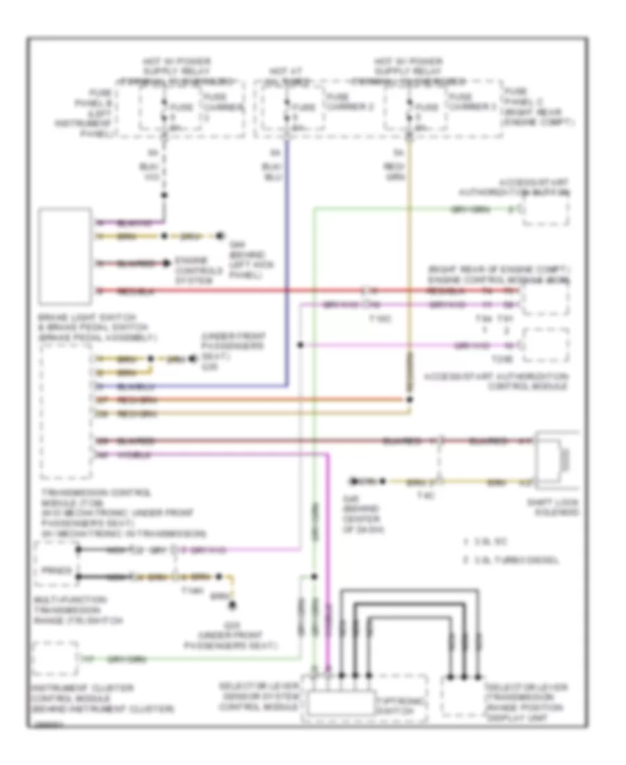
Shift Interlock Wiring Diagram for Audi Q7 Prestige S 2013
List of elements for Shift Interlock Wiring Diagram for Audi Q7 Prestige S 2013:
- (right rear of engine compt) engine control module (ecm)
- (under front passenger's seat) g35
- 3.0l sc
- 3.0l turbo diesel
- Access/start authorization button
- Access/start authorization control module
- Brake light switch & brake pedal switch (brake pedal assembly)
- Engine controls system
- Fuse 5a
- Fuse carrier
- Fuse carrier 2
- Fuse carrier 3
- Fuse panel b (left instrument panel)
- Fuse panel c (right rear engine compt)
- G35 (under front passenger's seat)
- G44 (behind left kick panel)
- G45 (behind center of dash)
- Hot at all times
- Instrument cluster control module (behind instrument cluster)
- Multi-function transmission range (tr) switch
- Nca
- Prnds
- Selector lever sensor system control module
- Selector lever transmission range position display unit
- Shift lock solenoid
- T10c
- T14h
- T20e
- T4c
- T91
- T94
- Tiptronic switch
- Transmission control module (tcm) (w/o mechatronic: under front passenger's seat) (w/ mechatronic: in transmission)
 English