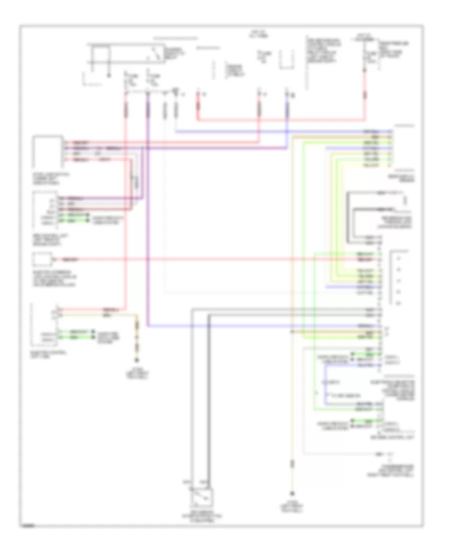
SHIFT INTERLOCK
Shift Interlock Wiring Diagram for Mercedes-Benz CLS550 2011
List of elements for Shift Interlock Wiring Diagram for Mercedes-Benz CLS550 2011:
- 58d
- Bls
- Can-c h
- Can-c l
- Can-ch
- Can-cl
- Chassis circuit 87 relay
- Computer data lines system
- Driver side sam control module w/ fuse & relay module (left side of engine compt)
- Eis (ezs) control unit
- Electric control unit (vgs)
- Electric steering lock control module (w/ keyless go) (on steering column)
- Electronic selector lever module control module (under center console)
- Engine circuit 87 relay
- Esp control unit (left rear of engine compt)
- Fuse 150a
- Fuse 5a
- Fuse 7.5a
- Gear display sensor
- Hot at all times
- Keyless-go start/stop button (if equipped)
- Nca
- Passenger-side sam control unit (right front footwell)
- Rear prefuse box (right side of trunk)
- Red
- Reversing and parking lock locking solenoid
- Stop lamp switch (under left side of dash)
- W/ keyless go
- W15/2 (left front footwell)
- X26/12
- X62-c1
- X62-c3
 English