
SHIFT INTERLOCKS
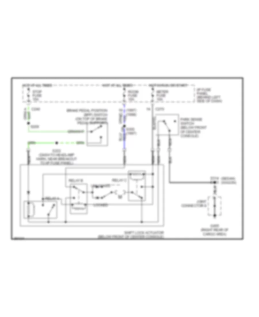
Shift Interlock Wiring Diagram for Mercury Tracer GS 1997
List of elements for Shift Interlock Wiring Diagram for Mercury Tracer GS 1997:
AIR CONDITIONINGANTI-LOCK BRAKESCRUISE CONTROLDEFOGGERSENGINE PERFORMANCECOMPUTER DATA LINESCOOLING FANANTI-THEFTEXTERIOR LIGHTSGROUND DISTRIBUTIONHEADLIGHTSHORNPOWER DOOR LOCKSPOWER WINDOWSINSTRUMENT CLUSTERINTERIOR LIGHTSPOWER DISTRIBUTIONRADIOPOWER MIRRORSWARNING SYSTEMSSHIFT INTERLOCKSTRANSMISSIONSTARTING/CHARGINGSUPPLEMENTAL RESTRAINTSWIPER/WASHER