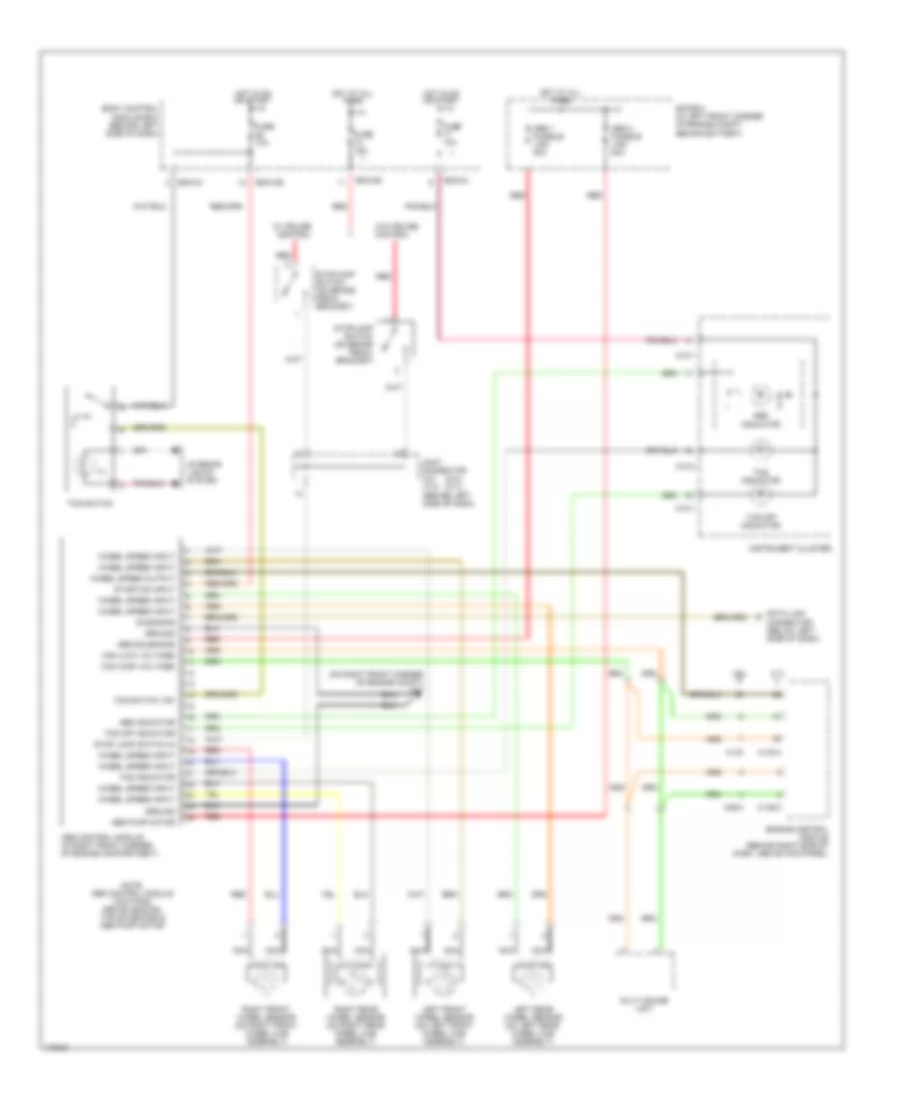
ANTI-LOCK BRAKES
Anti-lock Brakes Wiring Diagram for Hyundai Tiburon 2003
List of elements for Anti-lock Brakes Wiring Diagram for Hyundai Tiburon 2003:
- (2.0l) (2.7l)
- (on right front corner of engine compt) g17
- 2.0l
- 2.7l
- Abs 1 fusible link 30a
- Abs 2 fusible link 30a
- Abs control module (in right front corner of engine compartment)
- Abs indicator
- Abs pump motor
- Abs solenoids
- Bcm-ce
- Bcm-im
- Bcm-km
- Body control module box (behind left side of dash)
- C133
- C133-4
- C136-3
- C36-3
- Can (high voltage)
- Can (low voltage)
- Connector (below left side of dash)
- Data link
- Diagnosis
- E/r box (in left front corner of engine compt, behind battery)
- Engine control module (behind right side of dash, above kick panel)
- Fuse 10a
- Fuse 15a
- Ground
- Hot at all times
- Hot in on or start
- Ill
- Instrument cluster
- Interior lights system
- Joint connector c41 c141 (behind left side of dash)
- Left front wheel sensor (on left front wheel hub assembly)
- Left rear wheel sensor (on left rear wheel hub assembly)
- M10-1
- M10-2
- Multi gauge unit
- Nca
- Note: abs control module contains: abs solenoids, tcs solenoids & abs pump motor
- Red
- Right front wheel sensor (on right front wheel hub assembly)
- Right rear wheel sensor (on right rear wheel hub assembly)
- Start/on input
- Stop lamp switch in
- Stoplamp switch (on brake pedal bracket)
- Tcs indicator
- Tcs off indicator
- Tcs switch
- Tcs switch "on"
- W/ cruise control
- W/o cruise control
- Wheel speed input
- Wheel speed output
 Čeština
 Dansk
Dansk Deutsch
 Ελληνικά
 English
 English
 Español
 Suomi
Suomi Français
 Français
 עברית
עברית Hrvatski
 Magyar
 Italiano
 日本語
日本語 한국어
한국어 Nederlands
 Polski
 Português
 Português
 Română
 Русский
 Slovenščina
 Svenska
 Türkçe
 中文 (中国)
 Slovenčina