AIR CONDITIONING
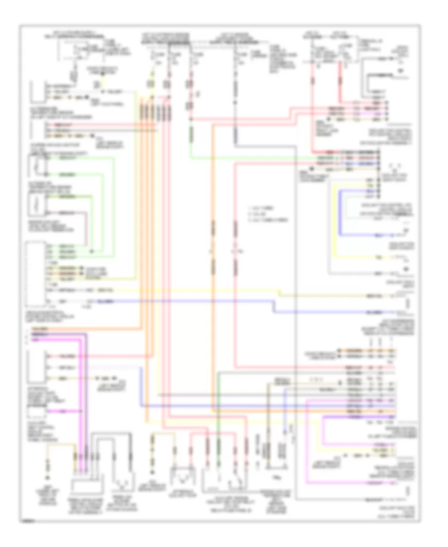
Automatic A/C Wiring Diagram, Basic (1 of 2) for Audi Q5 Premium 2013
 https://portal-diagnostov.com/license.html
Automotive Electricians Portal FZCO
Automotive Electricians Portal FZCO
https://portal-diagnostov.com/license.html
https://portal-diagnostov.com/license.html
Automotive Electricians Portal FZCO
Automotive Electricians Portal FZCO
List of elements for Automatic A/C Wiring Diagram, Basic (1 of 2) for Audi Q5 Premium 2013:
- (left rear of engine compt) g12
- (under left front of center console) g687
- 10a
- 13a
- 17a
- 2.0l turbo hybrid
- A/c compressor control module (on a/c compressor)
- Air flow door motor (left side of air intake housing)
- Center vent adjustment motor
- Center vent temperature sensor
- Climatronic control module
- Climatronic refrigerant shut-off valve (except 3.0l sc) (rear center of engine compt)
- Compressor magnetic clutch (2.0l turbo)
- Computer data
- Computer data lines system
- Coolant recirculation pump (except 2.0l turbo hybrid) (rear of engine compt)
- Defroster door motor (left side of hvac unit)
- Electric drive power & control electronics (right platinum chamber)
- Electrical a/c compressor
- Evaporator vent temperature sensor (right side of evaporator housing)
- Footwell door motor
- Footwell vent temperature sensor
- Fuse 10a
- Fuse 40a
- Fuse 5a
- Fuse carrier
- Fuse panel b (driver's side plenum chamber on electronics box)
- Fuse panel d (lower right side of dash)
- G12 (left rear of engine compt)
- Hot at all times
- Lines system
- Low temperature circuit coolant lamp (2.0l turbo hybrid)
- Nca
- Recirculation door motor (left side of air intake housing)
- Red
- Sunlight photo sensor
- T16i
- T17b
- T17e
- T17q
- T20e
- Temperature regulator door motor
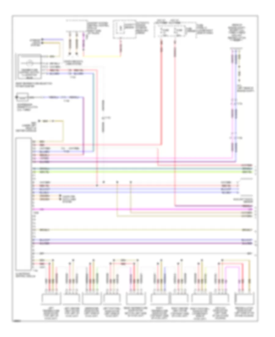
Automatic A/C Wiring Diagram, Basic (2 of 2) for Audi Q5 Premium 2013
List of elements for Automatic A/C Wiring Diagram, Basic (2 of 2) for Audi Q5 Premium 2013:
- (400w) (except 400w)
- (800w) coolant fan 2
- (not used)
- (or red)
- 11a
- 16a
- 2.0l turbo
- 2.0l turbo hybrid
- 3.0l sc
- A/c compressor regulator valve (except 2.0l turbo hybrid) (rear of a/c compressor)
- A/c pressure/ temperature sensor (on left side of a/c condenser)
- After-run coolant pump
- After-run coolant pump (except 3.0l sc) (hybrid: left front of engine)
- Auxiliary engine coolant (ec) pump relay (3.0l sc) (relay/fuse panel b)
- Auxiliary heat control module (behind right wheel housing)
- Charge air cooling pump (3.0l sc) (left front of engine compt)
- Computer data lines system
- Coolant fan (400w & 600w)
- Coolant fan (800w/1000w)
- Coolant fan 2 (600w)
- Coolant fan control (fc) control module (on cooling fan assembly)
- Coolant fan control (fc) control module 2 (800w/1000w) (on cooling fan assembly)
- Coolant recirculation pump (2.0l turbo hybrid) (rear of engine compt)
- Coolant shut-off valve (2.0l turbo hybrid)
- Engine control module (ecm) (in left plenum chamber)
- Engine coolant level (ecl) sensor (in coolant reservoir)
- Engine coolant temperature (ect) sensor (left side of engine)
- Fresh air blower (bottom of air intake housing)
- Fresh air blower control module (below blower motor assembly)
- Fuse 1 40a 60a
- Fuse 110a
- Fuse 15a
- Fuse 5a
- Fuse carrier
- Fuse panel b (driver's side plenum chamber on electronics box)
- Fuse panel c (lower left side of dash)
- G12 (left rear of engine compt)
- G639 (left kick panel)
- G685 (on right front long member)
- G687 (under left front of center console)
- Hot at all times
- Nca
- Outside air temperature sensor (behind front grille)
- Red
- T105
- T14f
- T16b
- T17i
- T17r
- T32b
- T5l
- T60
- T91
- T94
- Terminal 30 wire junction 2
- Vehicle electrical system control module (left side of dash)
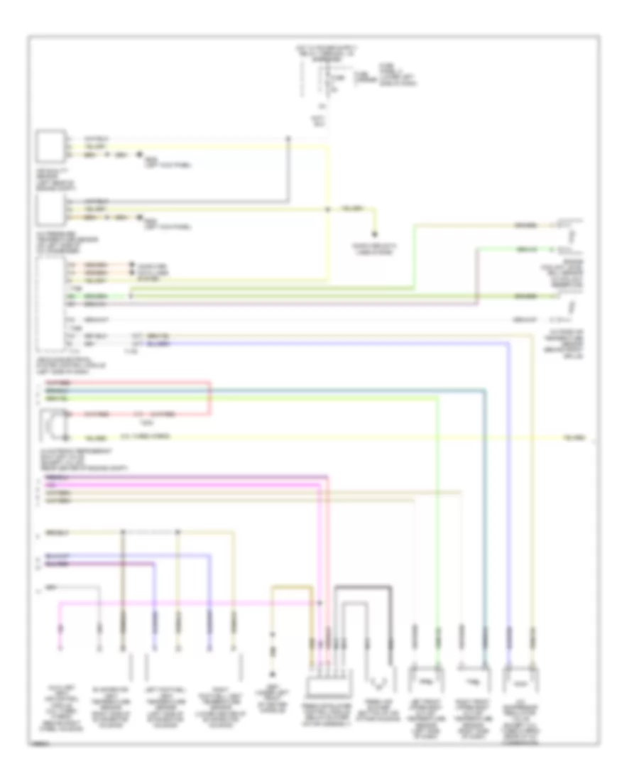
Automatic A/C Wiring Diagram, Comfort (1 of 3) for Audi Q5 Premium 2013
List of elements for Automatic A/C Wiring Diagram, Comfort (1 of 3) for Audi Q5 Premium 2013:
- (rear of engine compt) (except 2.0l turbo hybrid) coolant recirculation pump
- 10a
- Air flow door motor (left side of air intake housing)
- Automatic dimming interior rearview mirror
- Climatronic control module
- Comfort system central control module (right side of trunk) t32c
- Compressor magnetic clutch (2.0l turbo)
- Computer data lines system
- Defroster door motor (left side of hvac unit)
- Fuse 10a
- Fuse 40a
- Fuse carrier
- Fuse panel d (lower right side of dash)
- G12 (left rear of engine compt)
- G687 (under left front of center console)
- Hot at all times
- Humidity sensor
- Interior lights system
- Left center vent motor (top left of hvac unit)
- Left footwell door motor (left side of hvac unit)
- Left temperature door motor (top left of hvac unit)
- Nca
- Rear temperature door motor (bottom left side of hvac unit)
- Rear temperature selection potentiometer
- Recirculation door motor (left side of air intake housing)
- Red
- Right center vent motor (top right side of hvac unit)
- Right footwell door motor (lower right side of hvac unit)
- Right temperature door motor (top right side of hvac unit)
- Sunlight photo sensor
- T16i
- T17b
- T17d
- T17q
- T20e
- Temperature control switch illumination bulb
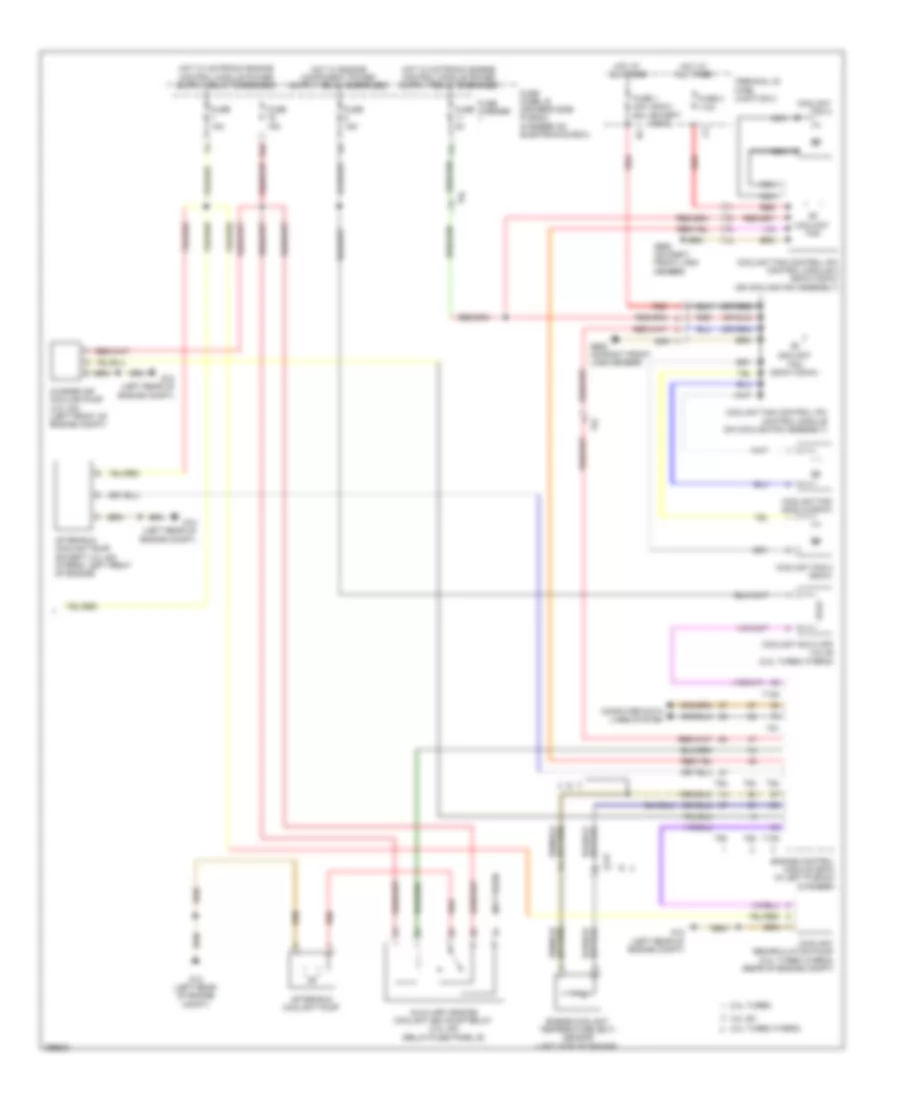
Automatic A/C Wiring Diagram, Comfort (2 of 3) for Audi Q5 Premium 2013
List of elements for Automatic A/C Wiring Diagram, Comfort (2 of 3) for Audi Q5 Premium 2013:
- 2.0l turbo hybrid
- A/c compressor regulator valve (except 2.0l turbo hybrid) (rear of a/c compressor)
- A/c pressure/ temperature sensor (on left side of a/c condenser)
- Air quality sensor (left rear of engine compt)
- Auxiliary heat air control module (2.0l turbo hybrid) (behind right wheel housing)
- Climatronic refrigerant shut-off valve (except 3.0l sc) (rear center of engine compt)
- Computer data lines system
- Engine coolant level (ecl) sensor (in coolant reservoir)
- Evaporator vent temperature sensor (right side of evaporator housing)
- Fresh air blower (bottom of air intake housing)
- Fresh air blower control module (below blower motor assembly)
- Fuse 5a
- Fuse carrier
- Fuse panel c (lower left side of dash)
- G639 (left kick panel)
- G687 (under left front of center console)
- Left footwell vent temperature sensor (left side of evaporator housing)
- Left front upper body outlet temperature sensor (left side of dash)
- Nca
- Outside air temperature sensor (behind front grille)
- Right footwell vent temperature sensor (lower center of evaporator housing)
- Right front upper body outlet temperature sensor (right side of dash)
- T16b
- T17i
- T17q
- T17r
- T32b
- Vehicle electrical system control module (left side of dash)
Automatic A/C Wiring Diagram, Comfort (3 of 3) for Audi Q5 Premium 2013
List of elements for Automatic A/C Wiring Diagram, Comfort (3 of 3) for Audi Q5 Premium 2013:
- (400w) (except 400w)
- (not used)
- (or red)
- 11a
- 16a
- 2.0l turbo
- 2.0l turbo hybrid
- 3.0l sc
- After-run coolant pump
- After-run coolant pump (except 3.0l sc) (hybrid: left front of engine)
- Auxiliary engine coolant (ec) pump relay (3.0l sc) (relay/fuse panel b)
- Charge air cooling pump (3.0l sc) (left front of engine compt)
- Computer data lines system
- Coolant fan
- Coolant fan (400w & 600w)
- Coolant fan (800w/1000w)
- Coolant fan 2
- Coolant fan 2 (600w)
- Coolant fan control (fc) control module (on cooling fan assembly)
- Coolant fan control (fc) control module 2 (800w/1000w) (on cooling fan assembly)
- Coolant recirculation pump (2.0l turbo hybrid) (rear of engine compt)
- Coolant shut-off valve (2.0l turbo hybrid)
- Engine control module (ecm) (in left plenum chamber)
- Engine coolant temperature (ect) sensor (left side of engine)
- Fuse 1 40a 60a
- Fuse 15a
- Fuse 2 110a
- Fuse 5a
- Fuse carrier
- Fuse panel b (driver's side plenum chamber on electronics box)
- G12 (left rear of engine compt)
- G685 (on right front long member)
- Hot at all times
- Nca
- Red
- T105
- T14f
- T5l
- T60
- T91
- T94
- Terminal 30 wire junction 2
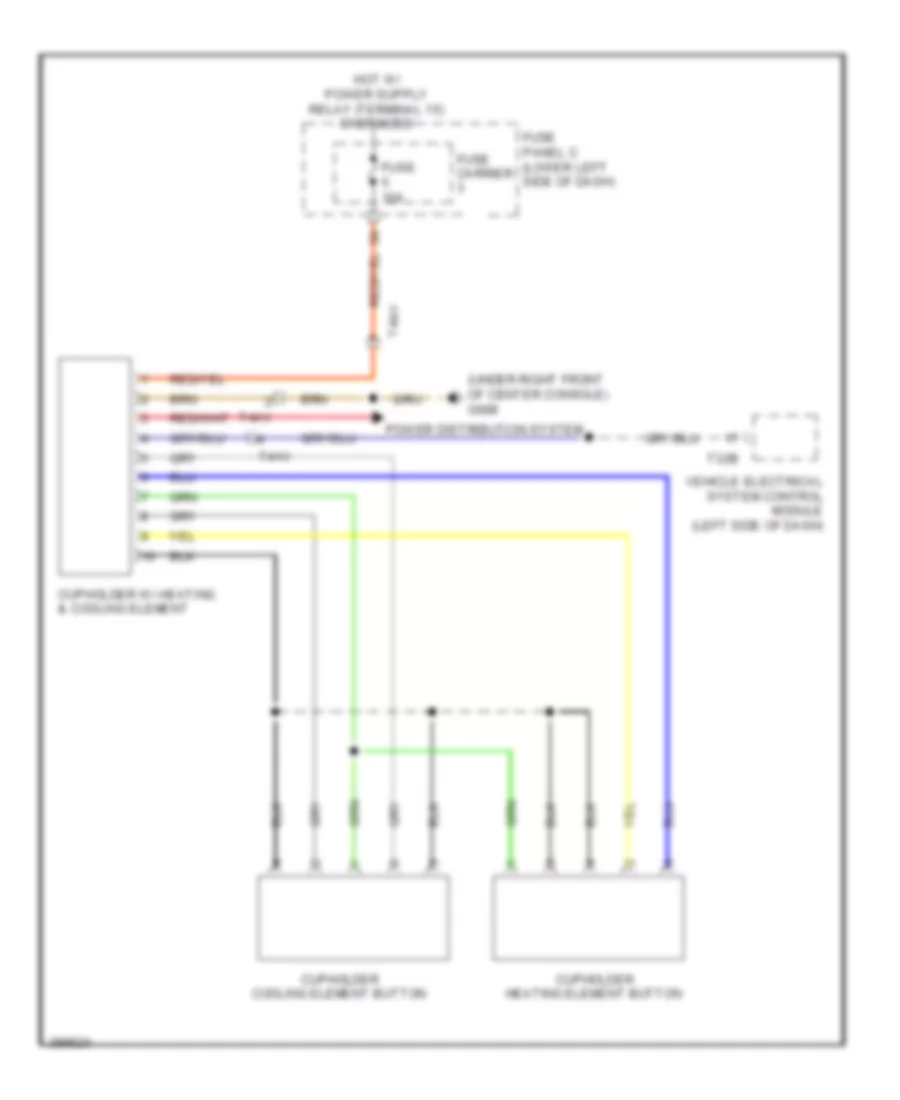
Heated And Cooled Cup Holder Wiring Diagram for Audi Q5 Premium 2013
List of elements for Heated And Cooled Cup Holder Wiring Diagram for Audi Q5 Premium 2013:
- (under right front of center console) g688
- Cupholder cooling element button
- Cupholder heating element button
- Cupholder w/ heating & cooling element
- Fuse 10a
- Fuse carrier
- Fuse panel c (lower left side of dash)
- Power distribution system
- T32b
- T4av
- Vehicle electrical system control module (left side of dash)

 Čeština
 Dansk
Dansk Deutsch
 Ελληνικά
 English
 English
 Español
 Suomi
Suomi Français
 Français
 עברית
עברית Hrvatski
 Magyar
 Italiano
 日本語
日本語 한국어
한국어 Nederlands
 Polski
 Português
 Português
 Română
 Русский
 Slovenščina
 Svenska
 Türkçe
 中文 (中国)