ANTI-LOCK BRAKES
Anti-lock Brakes Wiring Diagram (1 of 3) for Audi Q5 Premium 2013
 https://portal-diagnostov.com/license.html
Automotive Electricians Portal FZCO
Automotive Electricians Portal FZCO
https://portal-diagnostov.com/license.html
https://portal-diagnostov.com/license.html
Automotive Electricians Portal FZCO
Automotive Electricians Portal FZCO
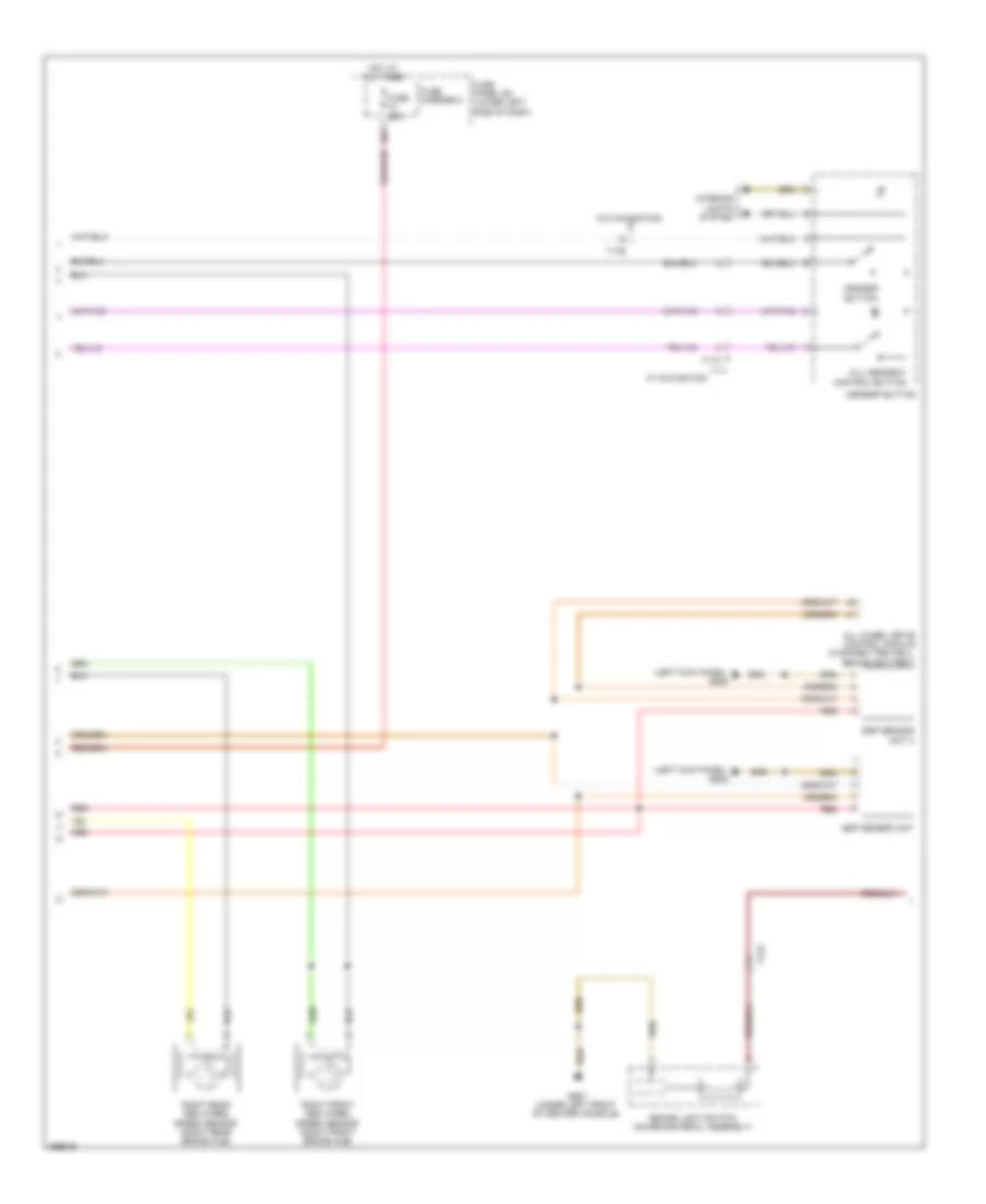
List of elements for Anti-lock Brakes Wiring Diagram (1 of 3) for Audi Q5 Premium 2013:
- (not used)
- 40a
- Abs control module (on abs hydraulic control unit)
- Abs control module fuse 1
- Abs hydraulic pump
- Auto hold button
- Computer data lines system
- Electro-mechanical parking brake button
- Fuse 10a
- Fuse 110a
- Fuse 5a
- Fuse carrier 1
- Fuse carrier 2
- Fuse panel sa (on battery positive terminal)
- Fuse panel sc (lower left side of dash)
- G671 (on lower left front long member)
- Hot at all times
- Left front abs wheel speed sensor (left front brake hub)
- Left rear abs wheel speed sensor (left rear brake hub)
- Red
- Roof rack recognition sensor (part of left roof railing)
- T17d
- T2ax
- Valve 1 pressure switch regulation high driving dynamics
- Valve 1 regulation switch driving dynamics
- Valve 2 pressure switch regulation high driving dynamics
- Valve 2 regulation switch driving dynamics
- Valve abs inlet left front
- Valve abs inlet left rear
- Valve abs inlet right front
- Valve abs inlet right rear
- Valve abs outlet left front
- Valve abs outlet left rear
- Valve abs outlet right front
- Valve abs outlet right rear
Anti-lock Brakes Wiring Diagram (2 of 3) for Audi Q5 Premium 2013
List of elements for Anti-lock Brakes Wiring Diagram (2 of 3) for Audi Q5 Premium 2013:
- (left kick panel) g639
- 10a
- All wheel drive control module (in spare tire well, behind battery)
- Asr/esp button
- Brake light switch (on brake pedal assembly)
- Esp sensor unit
- Esp sensor unit 2
- Fuse 25a
- Fuse carrier 2
- Fuse panel sc (lower left side of dash)
- G687 (under left front of center console)
- Hill descent control button
- Hot at all times
- Interior lights system
- Red
- Right front abs wheel speed sensor (right front brake hub)
- Right rear abs wheel speed sensor (right rear brake hub)
- T17c
- T17e
- W/ navigation
- W/o navigation
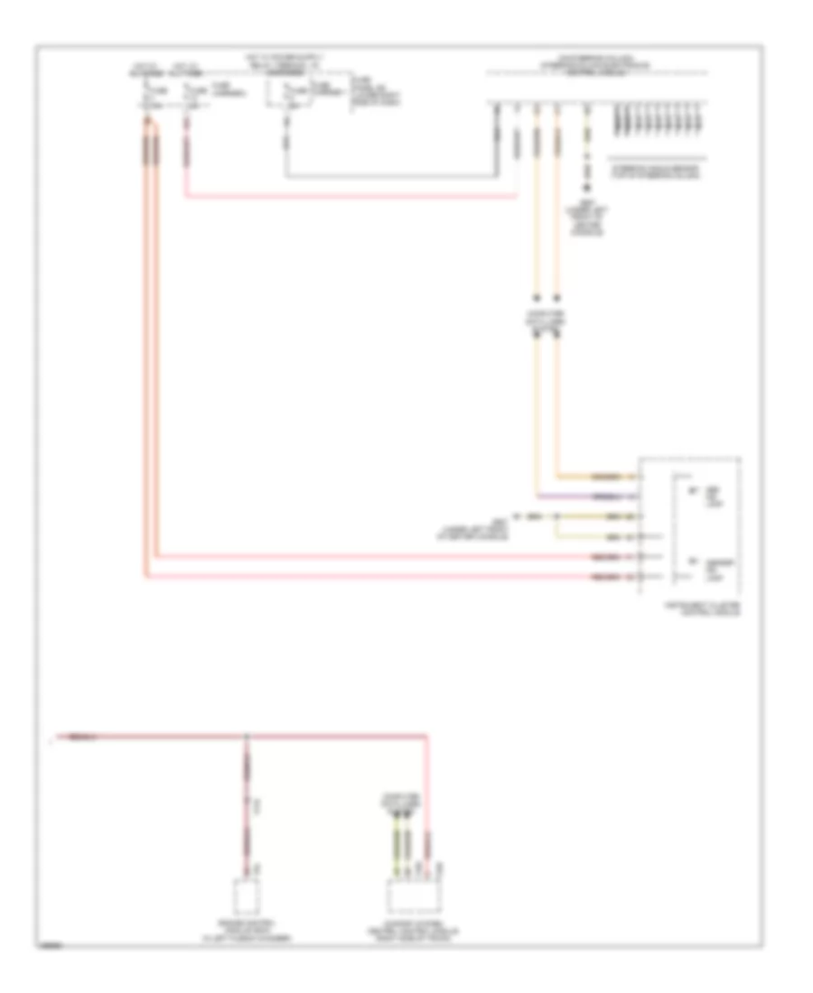
Anti-lock Brakes Wiring Diagram (3 of 3) for Audi Q5 Premium 2013
List of elements for Anti-lock Brakes Wiring Diagram (3 of 3) for Audi Q5 Premium 2013:
- (on steering column) steering column electronics control module
- Abs ind lamp
- Asr/esp ind lamp
- Comfort system central control module (right side of trunk)
- Computer data lines system
- Engine control module (ecm) (in left plenum chamber)
- Fuse 10a
- Fuse 5a
- Fuse carrier 1
- Fuse carrier 2
- Fuse panel sd (lower right side of dash)
- G687 (under left front of center console)
- Hot at all times
- Instrument cluster control module
- Nca
- Steering angle sensor (top of steering column)
- T17r
- T32c
- T32d
- T94

 Čeština
 Dansk
Dansk Deutsch
 Ελληνικά
 English
 English
 Español
 Suomi
Suomi Français
 Français
 עברית
עברית Hrvatski
 Magyar
 Italiano
 日本語
日本語 한국어
한국어 Nederlands
 Polski
 Português
 Português
 Română
 Русский
 Slovenščina
 Svenska
 Türkçe
 中文 (中国)