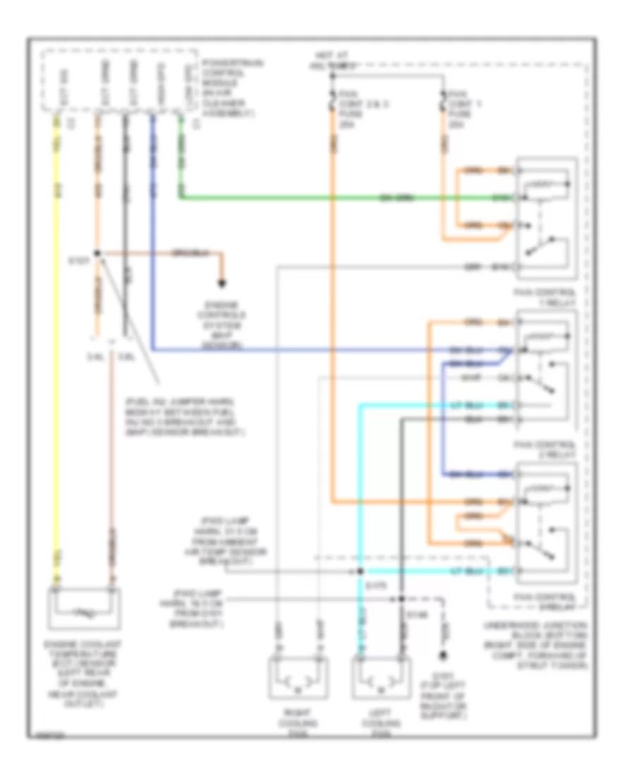
COOLING FAN
Cooling Fan Wiring Diagram for Chevrolet Impala 2003
List of elements for Cooling Fan Wiring Diagram for Chevrolet Impala 2003:
- (fuel inj jumper harn, midway between fuel inj no 3 breakout and (map) sensor breakout)
- (fwd lamp harn, 18.5 cm from g101 breakout)
- (fwd lamp harn, 31.5 cm from ambient air temp sensor breakout)
- 3.4l
- 3.8l
- B10
- C10
- Ect sig
- Engine controls system (map sensor)
- Engine coolant temperature (ect) sensor (left rear of engine, near coolant outlet)
- Fan cont 1 fuse 25a
- Fan cont 2 & 3 fuse 25a
- Fan control 1 relay
- Fan control 2 relay
- Fan control 3 relay
- G101 (top left front of radiator support)
- High spd
- Hot at all times
- Left cooling fan
- Low spd
- Powertrain control module (in air cleaner assembly)
- Right cooling fan
- S121
- S148
- S175
- Underhood junction block (bottom) (right side of engine compt, forward of strut tower)
 Čeština
 Dansk
Dansk Deutsch
 Ελληνικά
 English
 English
 Español
 Suomi
Suomi Français
 Français
 עברית
עברית Hrvatski
 Magyar
 Italiano
 日本語
日本語 한국어
한국어 Nederlands
 Polski
 Português
 Português
 Română
 Русский
 Slovenščina
 Svenska
 Türkçe
 中文 (中国)
 Slovenčina