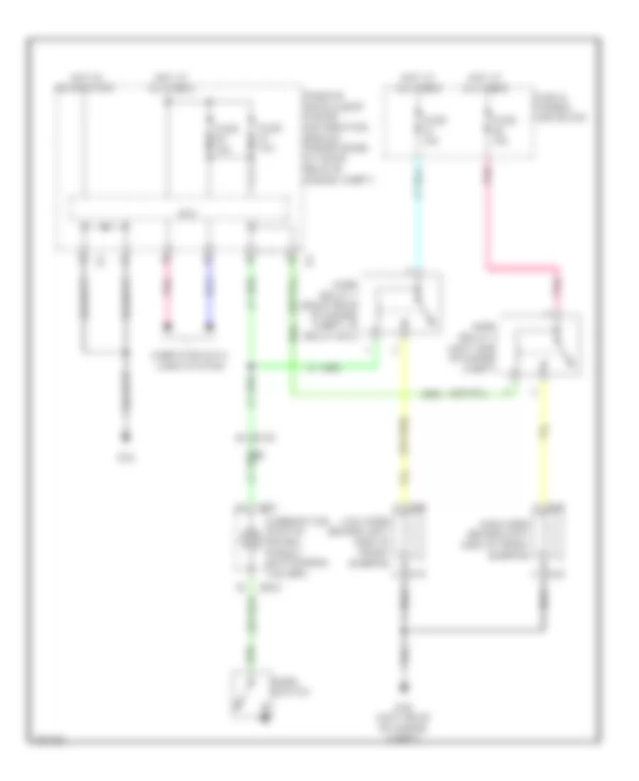
HORN
Horn Wiring Diagram for Infiniti G37 x 2013
List of elements for Horn Wiring Diagram for Infiniti G37 x 2013:
- (or nca)
- Combination switch (spiral cable) (in steering column)
- Computer data lines system
- Cpu
- E106
- E22
- E46 (left rear of engine compt)
- E61
- E62
- E69
- E70
- Fuse & fusible link block
- Fuse 10a
- Fuse 15a
- High horn (behind left side of front bumper)
- Horn relay 1 (right rear of engine compt, in relay box)
- Horn relay 2 (left side of engine compt)
- Horn switch
- Hot at all times
- Hot in on or start
- Ipdm e/r (intelligent power distribution module engine room) (at right rear of engine compt)
- Low horn (behind left side of front bumper)
- M303
- M36
- Pnk
 Čeština
 Dansk
Dansk Deutsch
 Ελληνικά
 English
 English
 Español
 Suomi
Suomi Français
 Français
 עברית
עברית Hrvatski
 Magyar
 Italiano
 日本語
日本語 한국어
한국어 Nederlands
 Polski
 Português
 Português
 Română
 Русский
 Slovenčina
 Svenska
 Türkçe
 中文 (中国)
 Slovenščina