DEFOGGERS
Defoggers Wiring Diagram for Hyundai XG350 L 2004
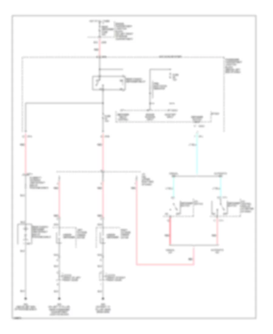
List of elements for Defoggers Wiring Diagram for Hyundai XG350 L 2004:
- A/c control module (in center of dash)
- A/c switch
- Automatic a/c
- B12
- Defogger relay control
- Defogger switch
- Defogger switch input
- Diversity antenna (above right end of package shelf)
- Engine compartment junction block (on left front of engine compartment)
- Engine running input
- Etacm
- Fuse 10a
- G03 (on left "a" pillar, near passenger compartment junction block)
- G05 (on right "a" pillar, near crash bar)
- G24 (above left end of package shelf)
- Hot at all times
- Hot in on or start
- I/p-a
- I/p-b
- I/p-j
- I/p-p
- I17-1
- J/c d12 (front of left front door)
- J/c d13 (front of right front door)
- J/c m36 (upper right end of dash)
- Jm09
- Left outside mirror motor
- M33-3
- M77-1
- M91
- Manual a/c
- Mirror defogger
- Nca
- Off
- On/start input
- Passenger compartment junction block (behind left end of dash)
- Pre- excitation resistor
- Rear defogger fuse 30a
- Rear window defogger (above right end of package shelf)
- Rear window defogger relay
- Red
- Right outside mirror motor
 Čeština
 Dansk
Dansk Deutsch
 Ελληνικά
 English
 English
 Español
 Suomi
Suomi Français
 Français
 עברית
עברית Hrvatski
 Magyar
 Italiano
 日本語
日本語 한국어
한국어 Nederlands
 Polski
 Português
 Português
 Română
 Русский
 Slovenčina
 Slovenščina
 Türkçe
 中文 (中国)
 Svenska