INSTRUMENT CLUSTER
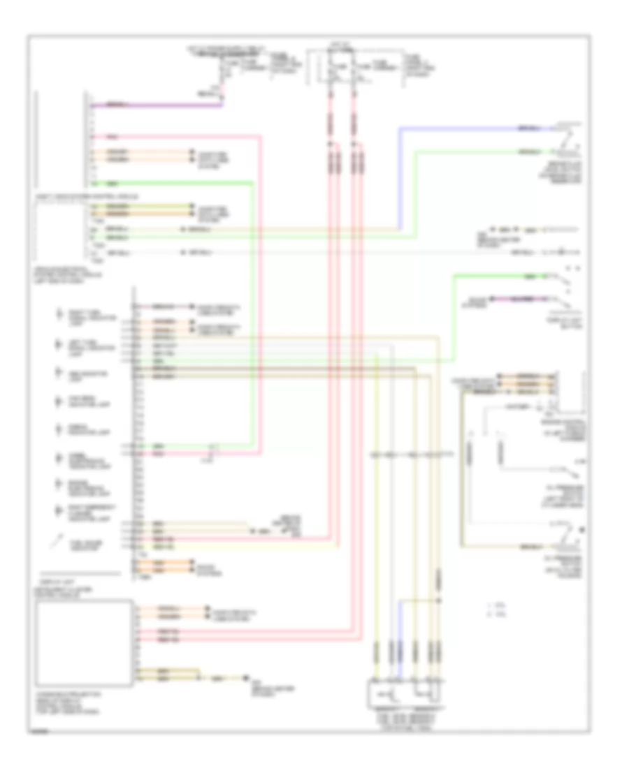
Instrument Cluster Wiring Diagram for Audi A6 2.0T 2012
List of elements for Instrument Cluster Wiring Diagram for Audi A6 2.0T 2012:
- (behind center of dash) g45
- 10a
- 2.0l
- 3.0l
- Abs indicator lamp
- Airbag indicator lamp
- Brake fluid level switch (on brake fluid reservoir)
- Computer data lines system
- Diesel electronics indicator lamp
- Display unit
- Display unit button
- Engine control module (in left plenum chamber)
- Engine electronics indicator lamp
- Fuel gauge indicator
- Fuel level sensor & fuel level sensor 2 (top of fuel tank)
- Fuse 5a
- Fuse carrier 1
- Fuse panel b (right end of dash)
- Fuse panel c (right end of dash)
- G45 (behind center of dash)
- High beam indicator lamp
- Hot at all times
- Instrument cluster control module
- Left turn signal indicator lamp
- Night vision system control module
- Oil pressure switch (left front of cylinder head)
- Oil pressure switch (on oil filter housing)
- Pnk
- Right emergency flasher indicator lamp
- Right turn signal indicator lamp
- Sensor 1
- Sensor 2
- Sound systems
- T16c
- T17f
- T17h
- T2bm
- T32
- T32a
- T32c
- T94
- Vehicle electrical system control module (left end of dash)
- Windshield projection head up display control module (top left side of dash)
 Čeština
 Dansk
Dansk Deutsch
 Ελληνικά
 English
 English
 Español
 Suomi
Suomi Français
 Français
 עברית
עברית Hrvatski
 Magyar
 Italiano
 日本語
日本語 한국어
한국어 Nederlands
 Polski
 Português
 Português
 Română
 Русский
 Slovenčina
 Slovenščina
 Türkçe
 中文 (中国)
 Svenska