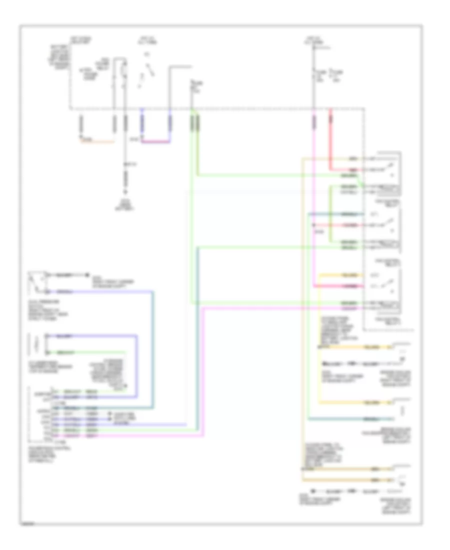
COOLING FAN
Cooling Fan Wiring Diagram, Except Hybrid for Ford Escape 2008
 https://portal-diagnostov.com/license.html
Automotive Electricians Portal FZCO
Automotive Electricians Portal FZCO
https://portal-diagnostov.com/license.html
https://portal-diagnostov.com/license.html
Automotive Electricians Portal FZCO
Automotive Electricians Portal FZCO
List of elements for Cooling Fan Wiring Diagram, Except Hybrid for Ford Escape 2008:
- (in engine control sensor & fuel charge wiring harness, before breakout to fuel injector 3)
- (in fuel shut off off solenoid wiring harness, near breakout to fuel injector 6)
- Acpsw
- Battery junction box (bjb) (left front of engine compt)
- C175b
- C175e
- Can+
- Can-
- Cec01
- Cec02
- Ch425
- Cht
- Computer data lines system
- Cooling fan relay
- Cooling fan resistor (2.3l) (left front of engine compt)
- Cylinder head temperature sensor (2.3l) (top of engine, on cylinder head)
- Dual pressure switch (right front of engine compt)
- Ect
- Engine control system
- Engine coolant temperature (ect) (3.0l) (rear of engine in water outlet)
- Engine cooling fan motor 1 (front of engine compt)
- Engine cooling fan motor 2 (front of engine compt)
- Fan ctrl
- Fuse 40a
- G102 (right front of engine compt)
- G103 (right front of engine compt)
- G104 (at left front corner of engine compt, near bjb)
- High speed fan control relay
- Hot at all times
- Hot in run or start
- Low speed fan control relay
- Pcm power diode
- Pcm power relay
- Power distribution system
- Powertrain control module (pcm) (3.0l: in recess on upper center of firewall) (2.3l: rear center of firewall)
- Re405
- Red
- S102
- S108 (in headlamp jumper wiring harness, near breakout to c139)
- S109
- S118
- S129
- Sigrtne
- Vdb04
- Vdb05
- Ve712
- Ve716
Cooling Fan Wiring Diagram, Hybrid for Ford Escape 2008
List of elements for Cooling Fan Wiring Diagram, Hybrid for Ford Escape 2008:
- (in dash panel to headlamp junction wiring harness, near breakout to battery junction box (bjb) s122
- (in dash panel to headlamp junction wiring harness, near breakout to battery junction box (bjb)) s120
- (in engine control sensor & fuel charge wiring harness, near breakout to coil on plug (cop) 4) s104
- Acpsw
- Battery junction box (bjb) (left rear of engine compt)
- C175b
- C175e
- Can+
- Can-
- Cec01
- Cec02
- Cec11
- Ch425
- Cht
- Computer data lines system
- Cylinder-head temperature sensor (top of engine)
- Dual pressure switch (right front of engine compt, near strut tower)
- Engine cooling fan dropping resistor 1 (left front of engine compt)
- Engine cooling fan motor 1 (left front of engine compt)
- Engine cooling fan motor 2 (right front of engine compt)
- Fan control relay 1
- Fan control relay 2
- Fan control relay 3
- Fc1
- Fc2
- Fc3
- Fuse 10a
- Fuse 40a
- G102 (right front corner of engine compt)
- G103 (right front corner of engine compt)
- G104 (near battery)
- Hot at all times
- Hot in run or start
- Pcm power diode
- Pcm power relay
- Powertrain control module (pcm) (rear center of firewall)
- Re405
- Red
- S115
- S125
- S126
- S134
- S140
- Sigrtne
- Vdb04
- Vdb05
- Ve712

 Čeština
 Dansk
Dansk Deutsch
 Ελληνικά
 English
 English
 Español
 Suomi
Suomi Français
 Français
 עברית
עברית Hrvatski
 Magyar
 Italiano
 日本語
日本語 한국어
한국어 Nederlands
 Polski
 Português
 Português
 Română
 Русский
 Slovenčina
 Slovenščina
 Türkçe
 中文 (中国)