CRUISE CONTROL
Cruise Control Wiring Diagram for Nissan Titan PRO-4X 2013
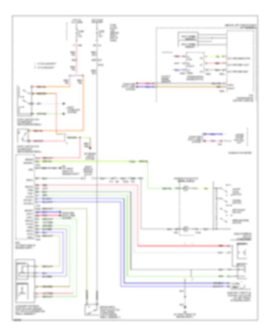
List of elements for Cruise Control Wiring Diagram for Nissan Titan PRO-4X 2013:
- (behind left side of dash) a/t assembly
- (right rear of engine) j/c f01
- 36g
- 65g m31
- 68g
- 69g
- 9p m4
- Accelerator pedal position (app) sensor (at top of accelerator pedal assembly)
- Aps1
- Aps2
- Ascd steering switch (if equipped)
- Ascdsw
- Avcc
- Avcc2
- Bncsw
- Brake
- Brake pedal position switch (if equipped) (top of brake pedal assembly)
- C1 (vin)
- C2 (vout)
- C3 (gnd) f506
- Can-h
- Can-l
- Cancel switch
- Close
- Combination meter
- Combination switch (spiral cable)
- Computer data lines system
- E152
- E16
- E9 (at right front of engine compt)
- Ecm (at right side of engine compt)
- Electric throttle control actuator (at left front of engine compt)
- Exterior lights system
- F14
- F502
- F503
- F505
- F54
- Fuse 10a
- Fuse block (j/b) (behind right end of dash)
- Gnd
- Gnd-a
- Gnd-a2
- Hot at all times
- Hot in on or start
- Input speed sensor 1
- Input speed sensor 2
- M102
- M24
- M30
- M31
- M60
- Motor 1
- Motor 2
- On/off (main) switch
- Open
- Out spd sen gnd
- Out spd sen vout
- Out spd sens pwr
- Output speed sensor
- Pnk
- Red
- Resume/accel switch
- Sensor 1
- Sensor 2
- Set/coast switch
- Shift interlock system
- Stop lamp switch (on bracket, above brake pedal)
- Tcm (transmission control module)
- Tps1
- Tps2
- Transmission range switch
- Unified meter control unit
- W/ column shift
- W/ floor shift
 Čeština
 Dansk
Dansk Deutsch
 Ελληνικά
 English
 English
 Español
 Suomi
Suomi Français
 Français
 עברית
עברית Hrvatski
 Magyar
 Italiano
 日本語
日本語 한국어
한국어 Nederlands
 Polski
 Português
 Português
 Română
 Русский
 Slovenčina
 Slovenščina
 Türkçe
 中文 (中国)
 Svenska