AIR CONDITIONING
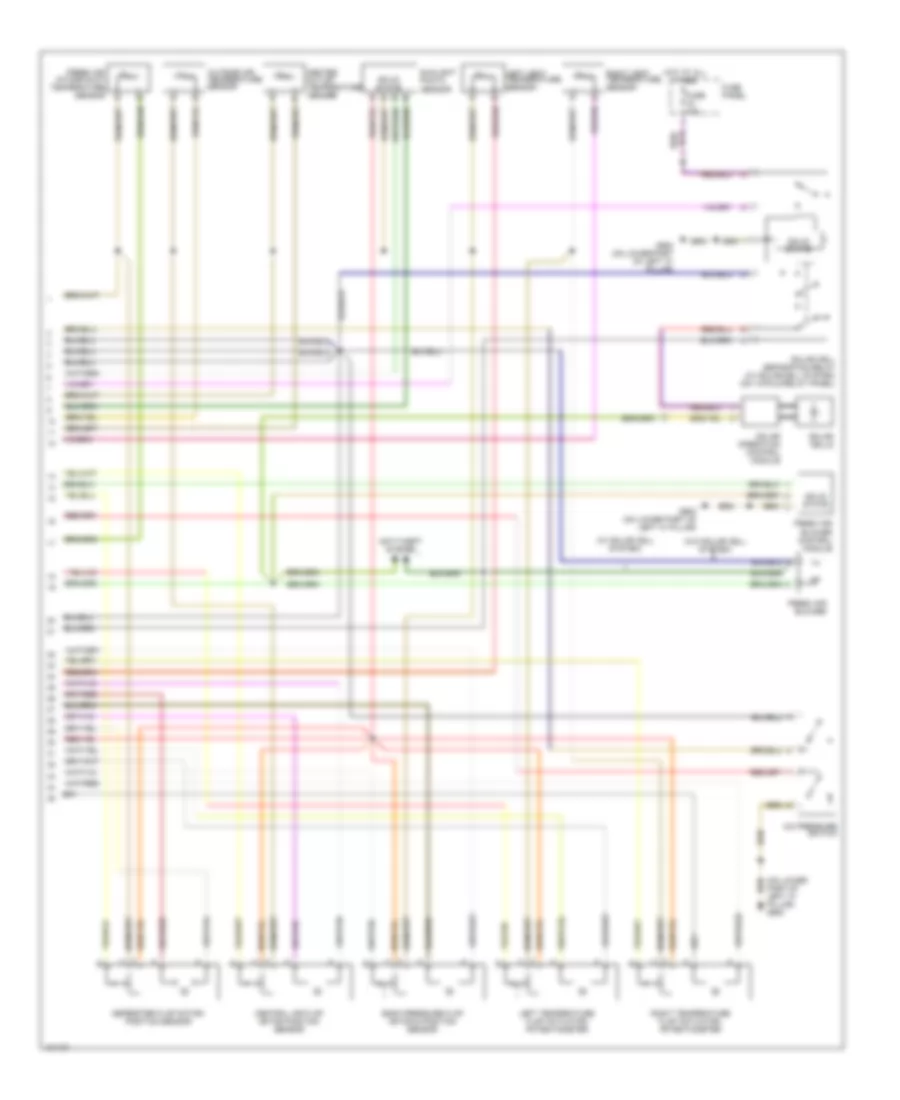
Automatic A/C Wiring Diagram, with Coolant Fan Control Module (1 of 2) for Audi allroad Quattro 2001
 https://portal-diagnostov.com/license.html
Automotive Electricians Portal FZCO
Automotive Electricians Portal FZCO
https://portal-diagnostov.com/license.html
https://portal-diagnostov.com/license.html
Automotive Electricians Portal FZCO
Automotive Electricians Portal FZCO
List of elements for Automatic A/C Wiring Diagram, with Coolant Fan Control Module (1 of 2) for Audi allroad Quattro 2001:
- (dlc) (partial) (below left side of dash)
- 8-fold relay panel
- A/c clutch
- A/c clutch relay (on 13-fold relay panel)
- A/c control module
- A10
- A11
- A12
- After-run coolant pump (2.7l, 2.8l)
- After-run coolant thermal switch (2.7l)
- Air quality sensor
- Anti-lock brakes system
- B10
- B11
- B12
- B13
- B14
- B15
- B16
- B17
- B18
- B19
- B20
- C10
- C11
- C12
- C13
- C14
- C15
- C16
- Coolant fan
- Coolant fan 2
- Coolant fan control (fc) thermal switch
- Coolant fc (fan control) control module
- D10
- D11
- D12
- D13
- D14
- D15
- D16
- Data link connector
- Defogger system
- Except 2.8l w/ front wheel drive
- Fuse 10a
- Fuse 30a
- Fuse 5a
- Fuse 60a
- Fuse panel
- G104 (left rear of engine compt)
- G900 (on lower left part of "a" pillar)
- Hot at all times
- Hot in run or start
- Hot in start
- Hot w/ load reduction relay energized
- Instrument cluster
- Interior lights system
- Motronic engine control module (ecm)
- Of "a" pillar) g900
- Solid state
- T32
- T32a
- Tachometer
- Wiper/washer system
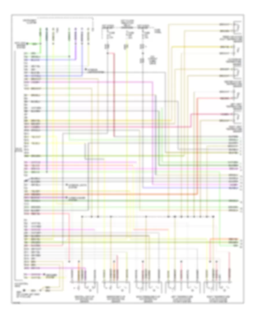
Automatic A/C Wiring Diagram, with Coolant Fan Control Module (2 of 2) for Audi allroad Quattro 2001
 https://portal-diagnostov.com/license.html
Automotive Electricians Portal FZCO
Automotive Electricians Portal FZCO
https://portal-diagnostov.com/license.html
https://portal-diagnostov.com/license.html
Automotive Electricians Portal FZCO
Automotive Electricians Portal FZCOList of elements for Automatic A/C Wiring Diagram, with Coolant Fan Control Module (2 of 2) for Audi allroad Quattro 2001:
- (on lower part of left "a" pillar) g900
- (w/ solar cell system)
- (w/o solar cell system)
- A/c pressure switch
- Anti-theft system
- Back pressure flap motor & position sensor
- Center outlet temperature sender
- Central air flap motor position sensor
- Defroster flap motor/ position sensor
- Fresh air blower
- Fresh air blower control module
- Fresh air intake duct temperature sensor
- Fuse 10a
- Fuse panel
- G900 (on lower part of left "a" pillar)
- Hot at all times
- Left temperature flap actuator/ potentiometer
- Left vent temperature sensor
- Outside air temperature sensor
- Right temperature flap actuator/ potentiometer
- Right vent temperature sensor
- Sensor
- Solar cell separation relay (w/ solar cell system) (on 13-fold relay panel)
- Solar cells
- Solar operation control module
- Solid state
- Sunlight photo
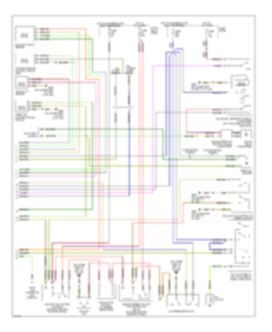
Automatic A/C Wiring Diagram, without Coolant Fan Control Module (1 of 2) for Audi allroad Quattro 2001
 https://portal-diagnostov.com/license.html
Automotive Electricians Portal FZCO
Automotive Electricians Portal FZCO
https://portal-diagnostov.com/license.html
https://portal-diagnostov.com/license.html
Automotive Electricians Portal FZCO
Automotive Electricians Portal FZCOList of elements for Automatic A/C Wiring Diagram, without Coolant Fan Control Module (1 of 2) for Audi allroad Quattro 2001:
- 2.8l w/front wheel drive
- A/c control head
- A10
- A11
- A12
- Anti-lock brakes system
- B10
- B11
- B12
- B13
- B14
- B15
- B16
- B17
- B18
- B19
- B20
- Back pressure flap motor position sensor
- C10
- C11
- C12
- C13
- C14
- C15
- C16
- Center outlet temperature sensor
- Central air flap motor position sensor
- D10
- D11
- D12
- D13
- D14
- D15
- D16
- Defogger system
- Defroster flap motor/position sensor
- Fresh air intake duct temperature sensor
- Fuse 10a
- Fuse 15a
- Fuse 30a
- Fuse panel
- G900 (on lower left part of "a" pillar)
- Hot in run or start
- Hot w/load reduction relay energized
- Instrument cluster
- Interior lights system
- Interior lights system
- Left temperature flap actuator/ potentiometer
- Left vent temperature sensor
- Outside air temperature sensor
- Right temperature flap actuator/ potentiometer
- Right vent temperature sensor
- Solid state
- T32
- T32a
- Wiper/washer system
Automatic A/C Wiring Diagram, without Coolant Fan Control Module (2 of 2) for Audi allroad Quattro 2001
 https://portal-diagnostov.com/license.html
Automotive Electricians Portal FZCO
Automotive Electricians Portal FZCO
https://portal-diagnostov.com/license.html
https://portal-diagnostov.com/license.html
Automotive Electricians Portal FZCO
Automotive Electricians Portal FZCOList of elements for Automatic A/C Wiring Diagram, without Coolant Fan Control Module (2 of 2) for Audi allroad Quattro 2001:
- (on lower part of left "a" pillar) g900
- (w/o solar cell system)
- (w/solar cell system)
- 2.8l w/front wheel drive
- 8-fold relay panel
- A/c clutch
- A/c clutch relay (on 13 fold relay panel, position 5)
- A/c pressure switch
- Air quality sensor
- All other models
- Anti-theft system
- Coolant fan
- Coolant fan control (fc) relay (on micro central electric panel)
- Coolant fan control (fc) series resistance
- Coolant fan control (fc) thermal switch
- Data link connector (dlc) (partial)
- Fresh air blower
- Fresh air blower control module
- Fuse 10a
- Fuse 30a
- Fuse 40a
- Fuse 5a
- Fuse panel
- G900 (on lower part of left "a" pillar)
- Hot at all times
- Hot w/load reduction relay energized
- Motronic engine control module (ecm)
- Nca
- Second speed coolant fan control (fc) relay (on micro central electric panel)
- Solar cell separation relay (if equipped) (on 13 fold relay panel, position 3)
- Solar cells (if equipped)
- Solar operation control module (if equipped)
- Solid state
- Sunlight photo sensor

 Čeština
 Dansk
Dansk Deutsch
 Ελληνικά
 English
 English
 Español
 Suomi
Suomi Français
 Français
 עברית
עברית Hrvatski
 Magyar
 Italiano
 日本語
日本語 한국어
한국어 Nederlands
 Polski
 Português
 Português
 Română
 Русский
 Slovenčina
 Slovenščina
 Svenska
 中文 (中国)
