TRANSMISSION
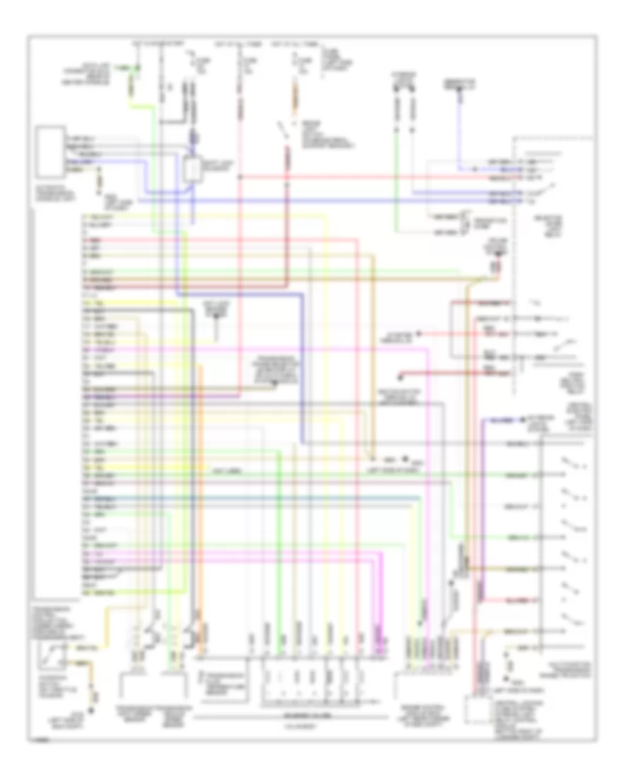
A/T Wiring Diagram for Audi A4 Quattro 1997
List of elements for A/T Wiring Diagram for Audi A4 Quattro 1997:
- (left side of dash)
- (not used)
- 11-13
- 15a
- 231a
- 38-39
- 45-50
- 50a
- 50z
- 56-87
- 87a
- Air conditioning system
- Anti-lock brakes system
- Automatic transmission console light
- Brake light switch (on brake pedal support bracket)
- Central electric panel (left side of dash)
- Central locking/ alarm system/ interior light delay control module (bottom right of luggage compt)
- Cruise control system
- Data link connector (dlc) (rear of center console)
- Engine control module (ecm) (left rear corner of eng compt)
- Exterior lights system
- Fuse 10a
- Fuse 15a
- Fuse panel (left side of dash)
- G102 (left side of eng compt)
- G202
- G202 (left side of dash)
- Generator terminal d+
- Hot at all times
- Hot in on or start
- Ignition switch terminal 50 (hot in start)
- Interior lights system
- Kickdown switch (on throttle housing)
- Multi-function transmission range (tr) switch
- Nca
- Park/ neutral position relay
- Protection diode
- Red
- Selector lever light relay
- Shift lock solenoid
- Solenoid valves
- Starter terminal 50
- Transmission control module (tcm) (under carpet, forward of passenger's seat)
- Transmission fluid temperature sensor
- Transmission input speed sensor
- Transmission range selector lever display or auto check system module
- Transmission vehicle speed sensor
- Valve body
 Čeština
 Dansk
Dansk Deutsch
 Ελληνικά
 English
 English
 Español
 Suomi
Suomi Français
 Français
 עברית
עברית Hrvatski
 Magyar
 Italiano
 日本語
日本語 한국어
한국어 Nederlands
 Polski
 Português
 Português
 Română
 Русский
 Slovenčina
 Slovenščina
 Svenska
 中文 (中国)
 Türkçe