TRANSMISSION
Transmission Wiring Diagram (1 of 2) for Hyundai Azera 2014

List of elements for Transmission Wiring Diagram (1 of 2) for Hyundai Azera 2014:
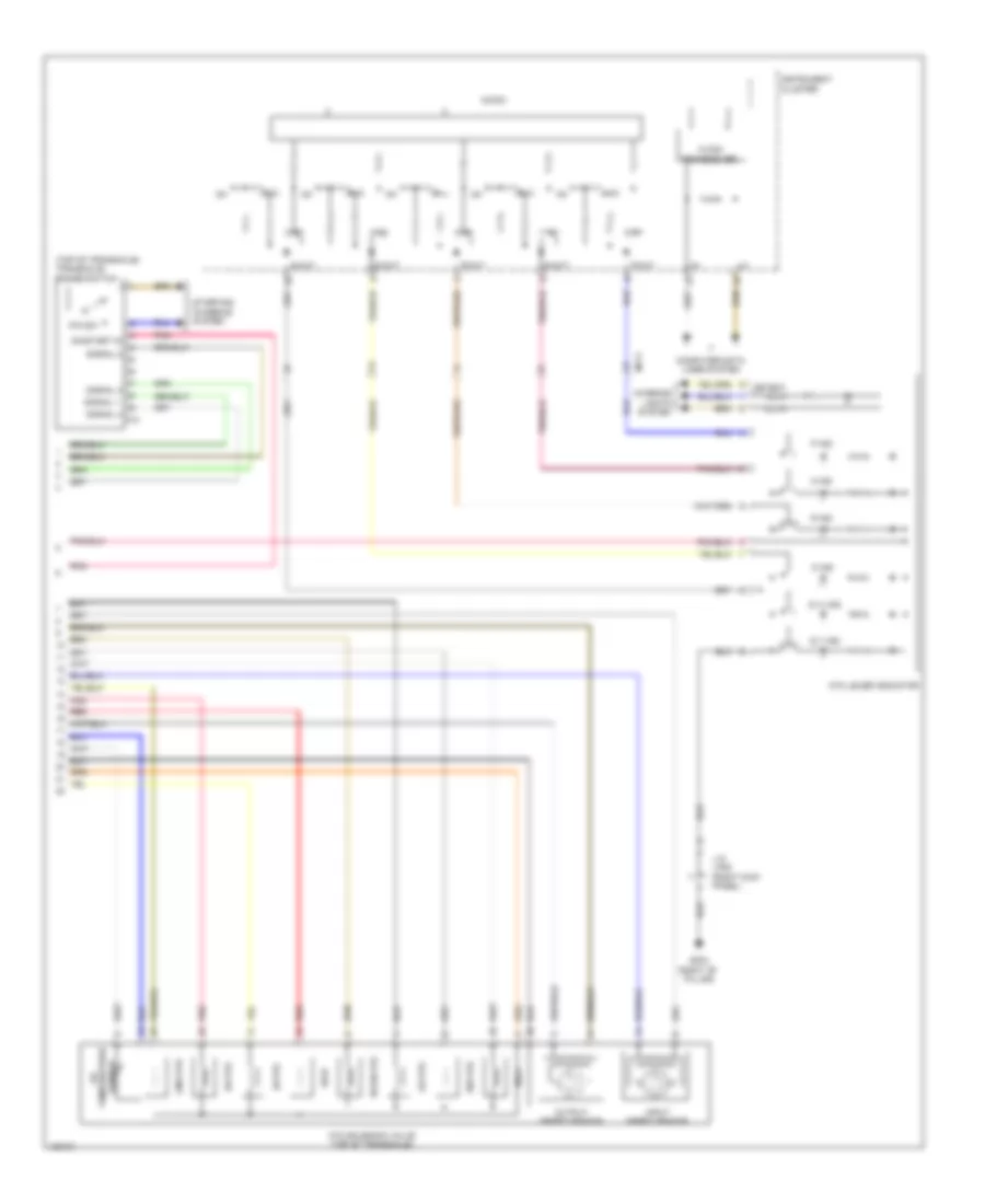
Transmission Wiring Diagram (2 of 2) for Hyundai Azera 2014
List of elements for Transmission Wiring Diagram (2 of 2) for Hyundai Azera 2014: