TRANSMISSION
A/T Wiring Diagram for Mercedes-Benz CLA250 2014

List of elements for A/T Wiring Diagram for Mercedes-Benz CLA250 2014:
- (+)
- (-)
- (left rear of engine compt) w11
- + 5v
- + u
- + v
- + w
- 30g
- 58ko
- Aux (+)
- Can b h
- Can b l
- Can c h
- Can c l
- Can e h
- Can e l
- Clutch k1 control valve
- Clutch k1 pressure sensor
- Clutch k2 control valve
- Clutch k2 pressure sensor
- Clutch temperature sensor
- Computer data lines system
- Direct select lever
- Double clutch transmission drive shaft rpm sensor
- Double clutch transmission hollow shaft rpm sensor
- Dual clutch transmission fully integrated transmission control unit (in transmission)
- Electric auxiliary oil pump
- Electronic ignition switch control unit (left center of dash)
- Engine compartment fuse & relay module (left side of engine compt)
- Engine speed rpm sensor
- Fuse 10a
- Fuse 25a
- Fuse 5a
- Gear control control valve, 1st/5th gear
- Gear control control valve, 2nd/4th gear
- Gear control control valve, 3rd/7th gear
- Gear control control valve, 6th/r gear
- Gear cylinder pressure control valve
- Gear ind
- Gnd
- Hall sensor 1
- Hall sensor 2
- Hall sensor 3
- Hot at all times
- Hot w/ circuit 87m relay energized
- Instrument cluster
- Me-sfi (me) control module (left front of engine compt)
- Motor
- Mr2
- Nca
- Park pawl control unit circuit 87 relay
- Park pawl lift solenoid
- Park pawl position sensor
- Park pawl switchover valve
- Prnd
- Red
- S1 sig
- S10
- S2 sig
- S3 sig
- Shift fork position sensor 1
- Shift fork position sensor 2
- Shift fork position sensor 3
- Shift fork position sensor 4
- Sig
- Steering column module control unit (top of steering column)
- System pressure control valve
- Transmission mode display
- Transmission oil cooling coolant circulation pump (bottom front of transmission)
- Vehicle interior fuse box (right front footwell)
- W12 (under left front of center console)
- W3/2 (left rear of engine compt)
- X25/13-c1
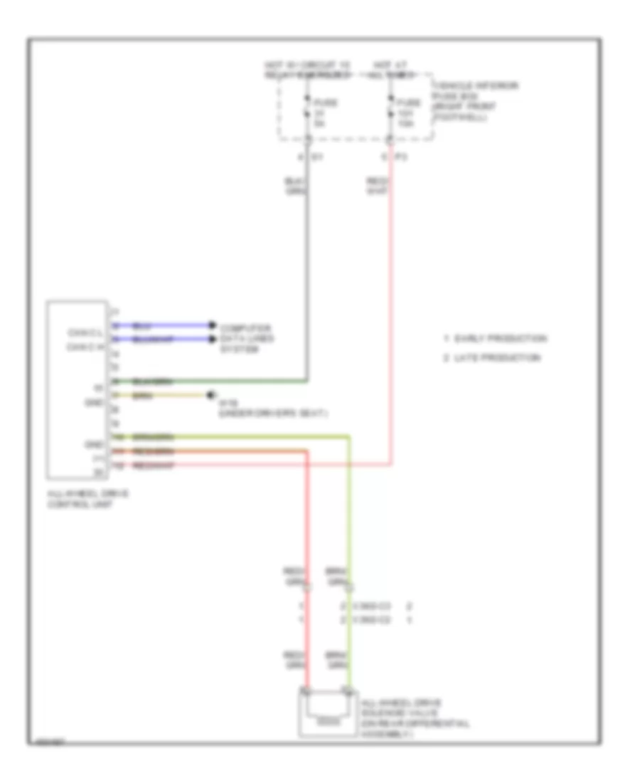
AWD Wiring Diagram for Mercedes-Benz CLA250 2014
List of elements for AWD Wiring Diagram for Mercedes-Benz CLA250 2014:
- (+)
- All-wheel drive control unit
- All-wheel drive solenoid valve (on rear differential assembly)
- Can c h
- Can c l
- Computer data lines system
- Early production
- Fuse 10a
- Fuse 5a
- Gnd
- Hot at all times
- Hot w/ circuit 15 relay energized
- Late production
- Vehicle interior fuse box (right front footwell)
- W18 (under driver's seat)
- X36/2-c2
- X36/2-c3