WARNING SYSTEMS
Seat Belt Warning Wiring Diagram for Mercedes-Benz CLS550 2011

List of elements for Seat Belt Warning Wiring Diagram for Mercedes-Benz CLS550 2011:
- 15g
- 31e
- Audible turn signal ind
- Brake fluid & parking brake warning lamp
- Brake fluid indicator switch (on brake fluid reservoir)
- Can l can h
- Can-b h
- Can-b l
- Computer data lines system
- Driver seat belt buckle restraint systems switch
- Driver side sam control module w/ fuse & relay module (left side of engine compt)
- Drv belt
- Esp & abs warning lamp
- Esp control unit (left rear of engine compt)
- Fuse 7.5a
- Hot at all times
- Hot w/ circuit 15 relay energized
- I13
- Instrument cluster
- Left front door contact switch (on left b-pillar)
- Multi-function display
- Nca
- Parking brake indicator switch (base of parking brake pedal assembly)
- Rear sam control module w/ fuse & relay module (left side of trunk)
- Restraint systems control module (under front of center console)
- Right front brake pad contact sensor (on right front brake assembly)
- Right rear brake pad contact sensor (on right rear brake assembly)
- Seat belt reminder lamp
- Tk vo re
- W15/1 (right front footwell)
- W15/2 (left front footwell)
- W2 (right front of engine compt)
- W26 (under center console)
- Warning buzzer
- X55/3-c2
- X62/6
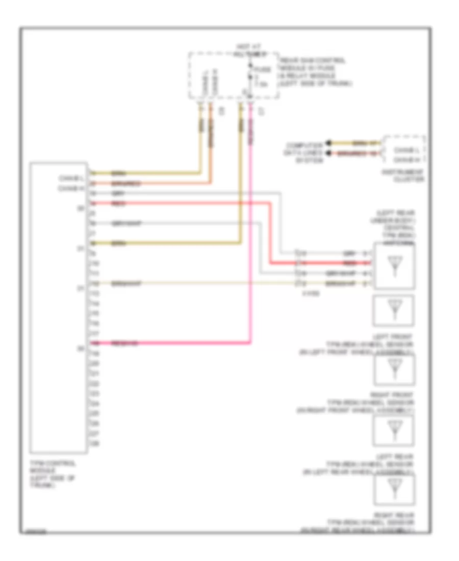
Tire Pressure Monitoring Wiring Diagram for Mercedes-Benz CLS550 2011
List of elements for Tire Pressure Monitoring Wiring Diagram for Mercedes-Benz CLS550 2011:
- (left rear under body) central tpm (rdk) antenna
- Can-b h
- Can-b l
- Computer data lines system
- Fuse 7.5a
- Hot at all times
- Instrument cluster
- Left front tpm (rdk) wheel sensor (in left front wheel assembly)
- Left rear tpm (rdk) wheel sensor (in left rear wheel assembly)
- Rear sam control module w/ fuse & relay module (left side of trunk)
- Red
- Right front tpm (rdk) wheel sensor (in right front wheel assembly)
- Right rear tpm (rdk) wheel sensor (in right rear wheel assembly)
- Tpm control module (left side of trunk)
- X1/50