Čeština
 Dansk
Dansk Deutsch
 Ελληνικά
 English
 English
 Español
 Suomi
Suomi Français
 Français
 עברית
עברית Hrvatski
 Magyar
 Italiano
 日本語
日本語 한국어
한국어 Nederlands
 Polski
 Português
 Português
 Română
 Русский
 Slovenčina
 Slovenščina
 Svenska
 Türkçe

BODY CONTROL MODULES
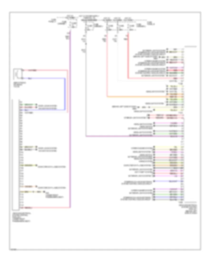
Comfort System Central Control Module Wiring Diagram for Audi Q7 Prestige S 2013
List of elements for Comfort System Central Control Module Wiring Diagram for Audi Q7 Prestige S 2013:

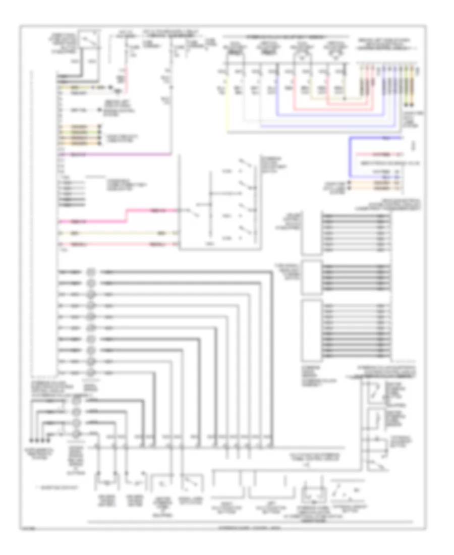
Steering Column Electronic Systems Control Module Wiring Diagram for Audi Q7 Prestige S 2013
List of elements for Steering Column Electronic Systems Control Module Wiring Diagram for Audi Q7 Prestige S 2013:
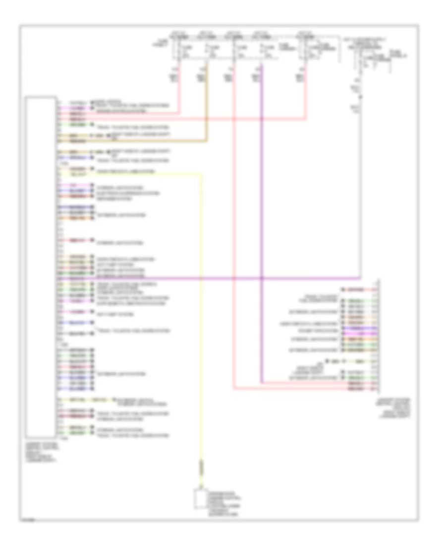
Vehicle Electrical System Control Module Wiring Diagram for Audi Q7 Prestige S 2013
List of elements for Vehicle Electrical System Control Module Wiring Diagram for Audi Q7 Prestige S 2013: