ENGINE PERFORMANCE
2.0L
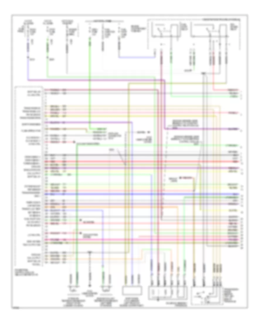
2.0L, Engine Performance Wiring Diagrams (1 of 3) for Mercury Tracer GS 1997
 https://portal-diagnostov.com/license.html
Automotive Electricians Portal FZCO
Automotive Electricians Portal FZCO
https://portal-diagnostov.com/license.html
https://portal-diagnostov.com/license.html
Automotive Electricians Portal FZCO
Automotive Electricians Portal FZCO
List of elements for 2.0L, Engine Performance Wiring Diagrams (1 of 3) for Mercury Tracer GS 1997:
- (engine harness, near breakout to constant control relay module) s109
- (engine harness, near breakout to powertrain control module) s231
- A/c on input
- A/c system
- Backup lamps
- C210
- C220
- C240
- Coil output
- Constant control relay module
- Cooling fans system
- Crank sens (+)
- Crank sens (-)
- Data link connector (dlc)
- Dlc #2 bus (+)
- Dlc #2 bus (-)
- Ect sens in
- Egr vac reg
- Engine compartment fuse box
- Engine coolant temperature sensor (left rear of engine)
- Engine fuse 15a
- Evap purge flow sensor (left front of engine compartment)
- Evap purge sens
- Flash eprom pwr
- Fuel injector fuse 10a
- Fuel pump fuse 30a
- Fuel pump mon
- Fuel pump relay
- G133 (near starter motor)
- Ground
- Hi fan ctrl
- Hot at all times
- Hot in run or start
- I/p fuse panel
- Iat sens in
- Intake air temperature sensor (front of air cleaner housing)
- Irm solenoid
- Lo fan ctrl
- Maf return
- Mil ind ctrl
- Nca
- Obd ii fuse 10a
- Octane adjust
- Pcm power relay
- Powertrain control module (below center of i/p)
- Psp sensor
- Rear ho2s in
- Red
- Room fuse 10a
- S101
- S102
- S107
- S204
- S209
- S218
- Shield ground
- Shift sol #1
- Shift sol #2
- Shift sol #3
- Solenoid assembly (transaxle)
- Stop fuse 15a
- Tach output sig
- Tcc sol
- Trans fluid temp
- Trans range-drive
- Trans range-rev
- Trans rnge-low
- Trans rnge-od
- Transmission range sensor (top left side of transaxle)
- Turbine sens (-)
- Vss (-)
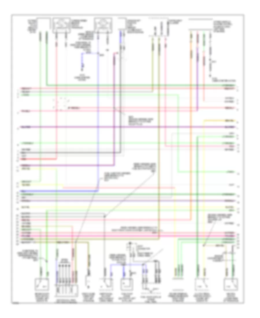
2.0L, Engine Performance Wiring Diagrams (2 of 3) for Mercury Tracer GS 1997
 https://portal-diagnostov.com/license.html
Automotive Electricians Portal FZCO
Automotive Electricians Portal FZCO
https://portal-diagnostov.com/license.html
https://portal-diagnostov.com/license.html
Automotive Electricians Portal FZCO
Automotive Electricians Portal FZCOList of elements for 2.0L, Engine Performance Wiring Diagrams (2 of 3) for Mercury Tracer GS 1997:
- (dashpanel to headlamp harness, near breakout to i/p fuse panel) s233
- (dashpanel to headlamp harness, near breakout to pcm) s242
- (engine harness, near breakout to octane adjust plug) s264
- (fuel injector harness, near breakout to ignition coil) s107
- (rear harness, near breakout to fuel pump module) s315
- (rear harness, near breakout to inertia fuel shutoff switch) s410
- (rear harness, near breakout to right front door courtesy lamp switch) s301
- Brake on/off (boo) switch (under left side of i/p)
- Clutch pedal position switch (under left side of i/p)
- Crankshaft position (ckp) sensor (lower right side of engine)
- Engine compartment fuse box
- Fuel pump diode (bottom of left 'b' pillar)
- Fuel pump module (inside fuel tank)
- G133 (near starter motor)
- Ignition coil pack (left side of engine)
- Inertia fuel shutoff (right side of cargo area)
- Instrument cluster
- Intake manifold runner control solenoid (imrc) (left side of engine)
- Joint connector (right rear of cargo area)
- Mil lamp
- Nca
- Neutral switch (lower rear of transaxle)
- Octane adjust plug (below center of i/p)
- Pnk
- Power steering pressure sensor (right side of engine)
- Radio noise capacitor (top left of engine)
- Red
- S101
- S205
- S230 (engine harness, near breakout to octane adjust plug)
- S403
- S404
- Spark plugs
- Tachometer
- Turbine speed sensor (top of transaxle)
- Upshift lamp
- Vehicle speed sensor (lower rear of transaxle)
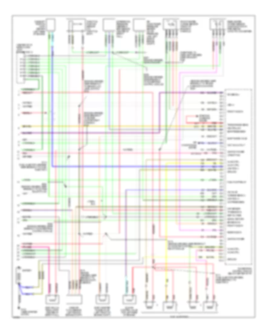
2.0L, Engine Performance Wiring Diagrams (3 of 3) for Mercury Tracer GS 1997
 https://portal-diagnostov.com/license.html
Automotive Electricians Portal FZCO
Automotive Electricians Portal FZCO
https://portal-diagnostov.com/license.html
https://portal-diagnostov.com/license.html
Automotive Electricians Portal FZCO
Automotive Electricians Portal FZCOList of elements for 2.0L, Engine Performance Wiring Diagrams (3 of 3) for Mercury Tracer GS 1997:
- (center of i/p, near floor) joint connector 10
- (dashpanel to headlamp harness, near grommet) s128
- (engine harness, near breakout to air bag diagnostic monitor) s224
- (engine harness, near breakout to brake fluid level switch) s124
- (engine harness, near breakout to engine compartment fuse box) s113
- (m/t only)
- (m/t)
- A/c press sens
- Air conditioner pressure sensor (on a/c pressure line, left side of engine comp't)
- Air conditioning system
- Battery
- Brake sw in
- Cam pos (+)
- Cam pos (-)
- Camshaft position (cmp) sensor (left rear of engine)
- Differential pressure feedback egr sensor (center of safety wall)
- Egr press sens
- Egr vacuum regulator (center of safety wall)
- Evap canister purge valve (left front of engine comp't)
- Evap purge valve
- Front heated oxygen sensor (front of engine in manifold)
- Front ho2s in
- Fuel injectors
- Fuel pump relay
- G133 (near starter motor)
- Ground
- Iac valve
- Idle air control valve (top left rear of engine)
- Ignition power
- Inj #1 ctrl
- Inj #2 ctrl
- Inj #3 ctrl
- Inj #4 ctrl
- Maf sensor
- Mass air flow sensor (left side of engine comp't)
- Nca
- Neutral sw
- Pnk
- Power b(+)
- Powertrain control module (below center of i/p)
- Rear heated oxygen sensor (in exhaust down pipe, behind catalytic converter)
- Rear ho2s in
- Red
- Ref voltage
- S110 (engine harness, near breakout to engine compt., fuse box)
- S111 (fuel injector harness, near breakout to injector 3)
- S112 (engine harness, near breakout to constant control relay module)
- S114 (fuel injector harness, near breakout to fuel injector 3
- S225 (engine harness, near breakout to powertrain control module)
- S226 (engine harness, near breakout to powertrain control module)
- S227 (engine harness, near grommet)
- S228 (engine harness, near breakout to octane adjust plug)
- Signal return
- Starting/ charging system (a/t)
- Tan
- Throttle position sensor (on throttle body)
- Tp sensor in
- Trans range sens
- Turbine sens (+)
- Upshift ind
- Vss (+)
- Wot a/c cutout

 Čeština
 Dansk
Dansk Deutsch
 Ελληνικά
 English
 English
 Español
 Suomi
Suomi Français
 Français
 עברית
עברית Hrvatski
 Magyar
 Italiano
 日本語
日本語 한국어
한국어 Nederlands
 Polski
 Português
 Português
 Română
 Русский
 Slovenčina
 Slovenščina
 Svenska
 Türkçe
