Čeština
 Dansk
Dansk Deutsch
 Ελληνικά
 English
 English
 Español
 Suomi
Suomi Français
 Français
 עברית
עברית Hrvatski
 Magyar
 Italiano
 日本語
日本語 한국어
한국어 Nederlands
 Polski
 Português
 Português
 Română
 Русский
 Slovenčina
 Slovenščina
 Svenska
 Türkçe

EXTERIOR LIGHTS
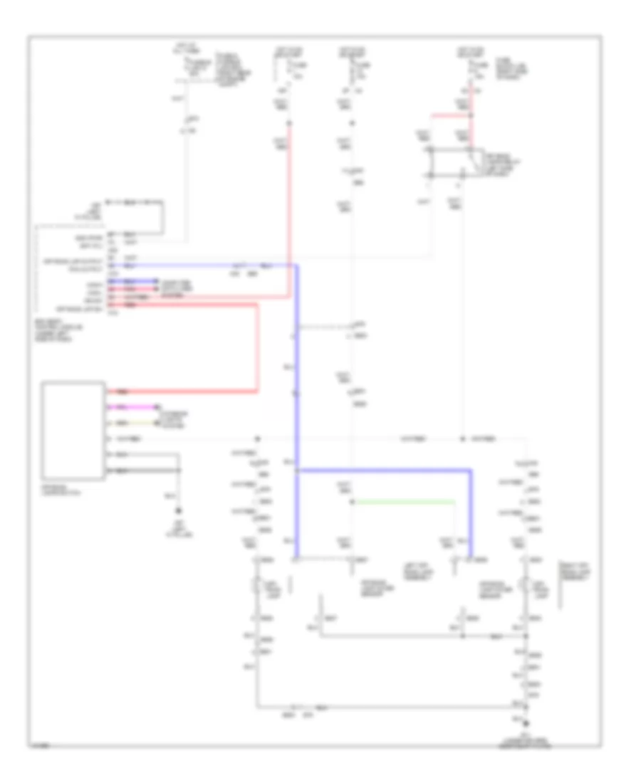
Backup Lamps Wiring Diagram for Nissan Xterra PRO-4X 2013


List of elements for Backup Lamps Wiring Diagram for Nissan Xterra PRO-4X 2013:
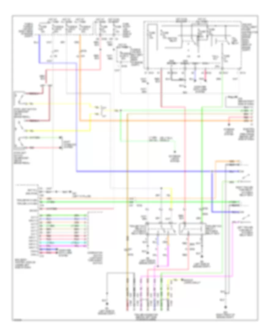
Exterior Lamps Wiring Diagram (1 of 2) for Nissan Xterra PRO-4X 2013
List of elements for Exterior Lamps Wiring Diagram (1 of 2) for Nissan Xterra PRO-4X 2013:
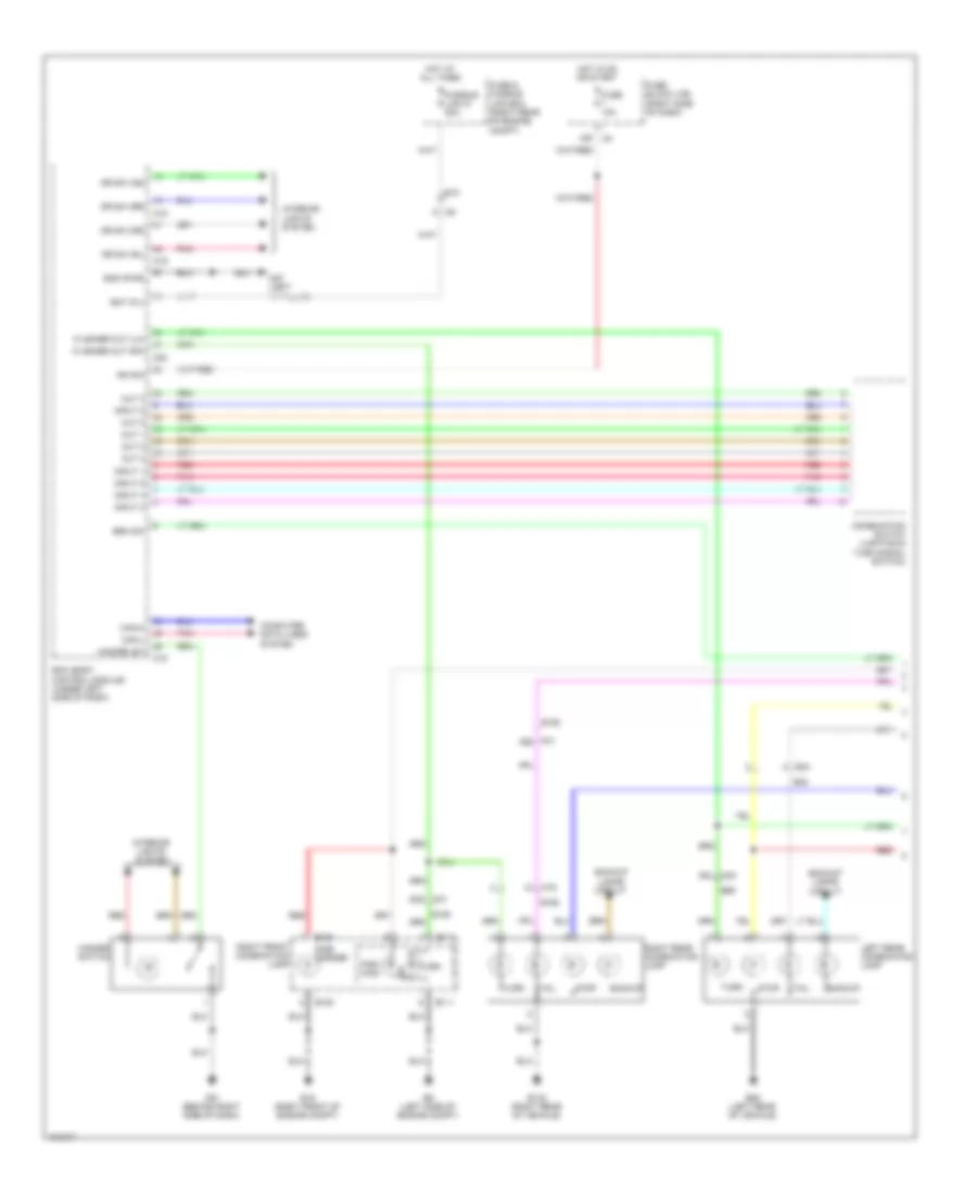
Exterior Lamps Wiring Diagram (2 of 2) for Nissan Xterra PRO-4X 2013
List of elements for Exterior Lamps Wiring Diagram (2 of 2) for Nissan Xterra PRO-4X 2013:
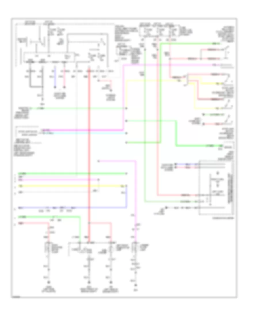
Off-Road Lighting Wiring Diagram for Nissan Xterra PRO-4X 2013
List of elements for Off-Road Lighting Wiring Diagram for Nissan Xterra PRO-4X 2013:
Trailer Tow Wiring Diagram for Nissan Xterra PRO-4X 2013
List of elements for Trailer Tow Wiring Diagram for Nissan Xterra PRO-4X 2013: