POWER DISTRIBUTION
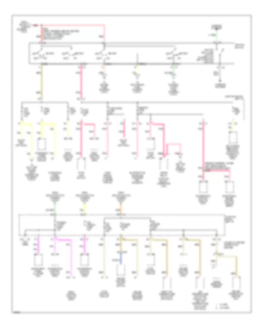
Power Distribution Wiring Diagram (1 of 5) for Chevrolet Impala 2003
 https://portal-diagnostov.com/license.html
Automotive Electricians Portal FZCO
Automotive Electricians Portal FZCO
https://portal-diagnostov.com/license.html
https://portal-diagnostov.com/license.html
Automotive Electricians Portal FZCO
Automotive Electricians Portal FZCO
List of elements for Power Distribution Wiring Diagram (1 of 5) for Chevrolet Impala 2003:
- (dash harness, approximately 16 cm (6 in) from circuit breaker 3) s244
- Audio amplifier
- B10
- Battery
- Circuit breaker 1 30a
- Circuit breaker 2 30a
- Circuit breaker 3 50a
- Cooling fans fuse 60a
- Crank relay
- D11
- Digital radio receiver
- Driver outside rearview mirror
- Electronic brake control module (ebcm)
- F10
- F11
- From crank relay o (diagram 2 of 5)
- From right i/p 3 fuse (diagram 1 of 5)
- Fuse block- seo (w/9c1/9c3/9c6)
- Fusible link (10 ga-rust)
- Fusible link (14 ga-gray) (w/9c1,9c3, 9c6)
- Fusible link (16 ga-black) (w/anti-lock brakes system)
- G203 (under dash, to right of steering column, on dash support bracket)
- Generator
- Harness, approx 10.5 cm (4 in) from ambient air temperature sensor breakout, toward right headlamp) s174
- Htd mir fuse 10a
- Ign rly relay
- Ign sw fuse 60a
- Junction block- left i/p
- Junction block- rear compartment (seo)
- Junction block- right i/p
- Junction block- underhood (bottom)
- Junction block- underhood (top)
- Left i/p fuse 60a
- Passenger outside rearview mirror
- Pnk
- Radio
- Radio antenna module
- Radio fuse 15a
- Rear defog circuit breaker 30a
- Rear defog relay
- Red
- Right i/p 1 fuse 60a
- Right i/p 2 fuse 60a
- Right i/p 3 fuse 60a
- S370 (body wiring harness, right side of floor)
- Seo relay
- Starter motor
- To fan cont 1 fuse (diagram 3 of 5)
- To ignition switch (diagram 2 of 5)
- To junction block- left i/p (diagram 3 of 5)
- To junction block- right i/p (diagram 4 of 5)
- To junction block- right i/p (diagram 5 of 5)
- To junction block- underhood (top) (diagram 5 of 5)
- To rear defog relay (diagram 1 of 5)
- To splice s177 (diagram 3 of 5)
- U/hood fuse 60a
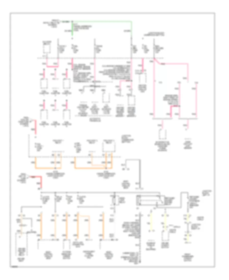
Power Distribution Wiring Diagram (2 of 5) for Chevrolet Impala 2003
 https://portal-diagnostov.com/license.html
Automotive Electricians Portal FZCO
Automotive Electricians Portal FZCO
https://portal-diagnostov.com/license.html
https://portal-diagnostov.com/license.html
Automotive Electricians Portal FZCO
Automotive Electricians Portal FZCOList of elements for Power Distribution Wiring Diagram (2 of 5) for Chevrolet Impala 2003:
- (engine harness, lower left rear side of engine compartment) s169
- (not used)
- A/c cruise fuse 10a
- A/c fan fuse 20a
- A10
- A11
- A12
- Abs/pcm fuse 10a
- Acc
- Accy
- Air temperature actuator (manual a/c) left air temperature actuator (optional)
- Bcm fuse 10a
- Body control module (bcm)
- C201
- C373
- Cig/ aux fuse 10a
- Crank
- Crank relay
- Cruise control module (ccm)
- Cruise control on/off switch
- Cruise control release switch
- Cruise fuse 2a
- D11
- D12
- Driver information center (dic)
- Electronic brake control module (ebcm)
- Evaporative emissions canister vent solenoid
- F10
- From ign sw fuse (diagram 1 of 5)
- From ignition switch (diagram 2 of 5)
- Hvac control module
- Ign 0
- Ign 1
- Ign 3
- Ignition key alarm switch (closed with key in ignition switch)
- Ignition switch
- Ignition switch)
- Inflatable restraint sensing & diagnostic module (sdm)
- Inside rearview mirror
- Instrument panel cluster (ipc)
- Junction block- left i/p
- Junction block- underhood (top)
- Off
- Pcm (crank) fuse 10a
- Pcm/bcm clstr fuse 10a
- Pnk
- Powertrain control module (pcm)
- Red
- Right air temperature actuator (optional)
- S234 (dash harness, behind center of dash, approximately 32.5 cm (13 in) from red
- Srs fuse 10a
- Start
- Stop fuse 10a
- Stop lamp switch
- To auxiliary power drop connector (diagram 5 of 5)
- To cruise fuse (diagram 2 of 5)
- To ignition relay (diagram 1 of 5)
- To pcm (crank) fuse (diagram 2 of 5)
- To pcm/bcm/ clstr fuse (diagram 2 of 5)
- Turn signal fuse 15a
- Turn signal/ hazard flasher module
- W/ gps
- W/display driver information center
- W/o gps
- Warning systems
- Windshield wiper system module
- Windshield wiper/ washer switch
- Wsw fuse 25a
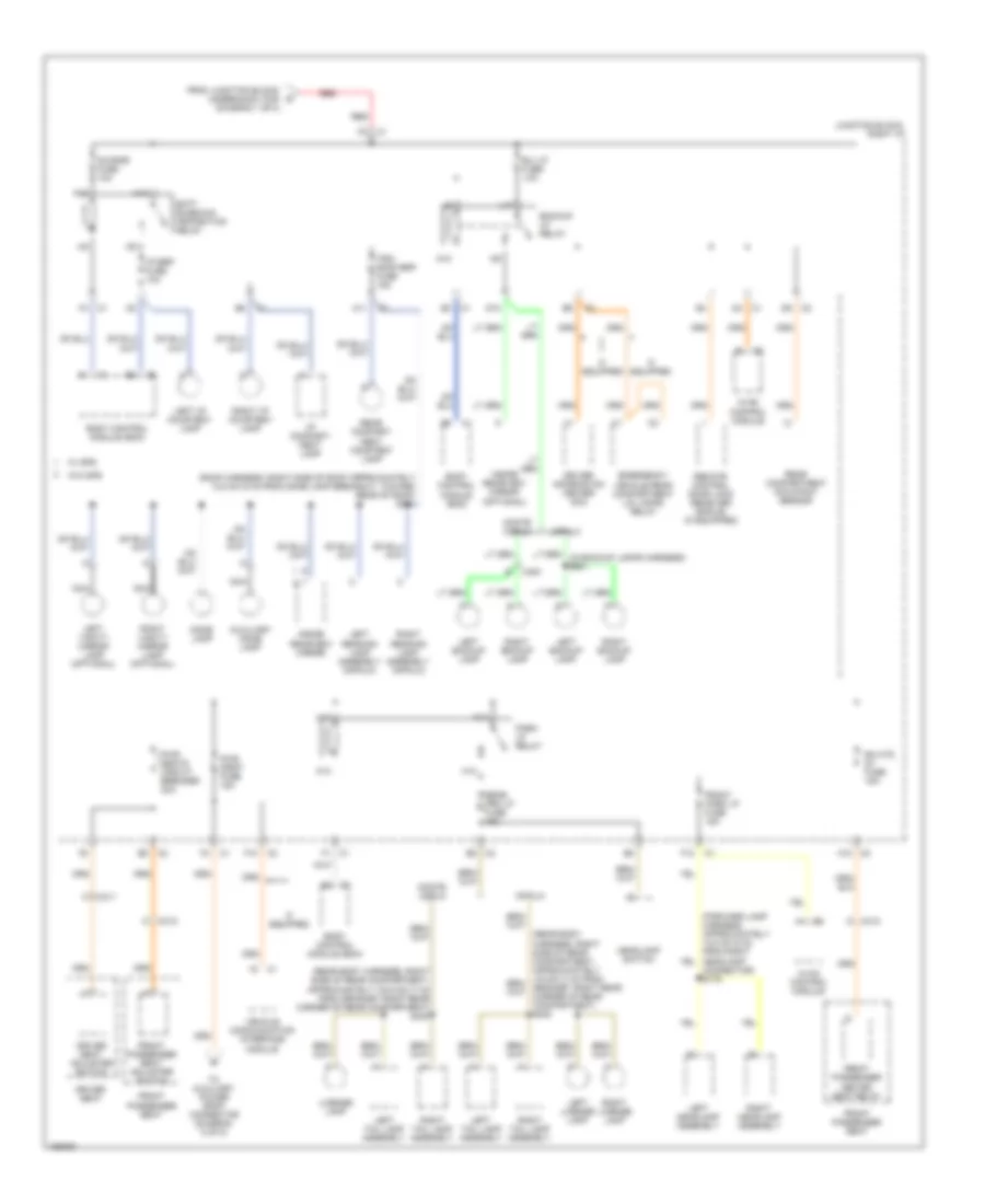
Power Distribution Wiring Diagram (3 of 5) for Chevrolet Impala 2003
 https://portal-diagnostov.com/license.html
Automotive Electricians Portal FZCO
Automotive Electricians Portal FZCO
https://portal-diagnostov.com/license.html
https://portal-diagnostov.com/license.html
Automotive Electricians Portal FZCO
Automotive Electricians Portal FZCOList of elements for Power Distribution Wiring Diagram (3 of 5) for Chevrolet Impala 2003:
- (3.8l-engine harness at egr valve breakout) (3.4l-engine harness, left front of engine compartment, approximately 10.5 cm (4 in) from 24 cavity black in-line connector) s157
- (dash harness, behind left side of dash, approx. 4 cm (2 in) from body computer module breakout) s236
- (diagram 1 of 5)
- (engine harn, right front of engine approx 4.7 cm (2 in) from c112) s131
- (under dash, to right of steering column, on i/p support bracket) g201
- 1-2 shift solenoid (1-2 ss) valve
- 2-3 shift solenoid (2-3 ss) valve
- 3.4l
- 3.8l
- A/c cmpr relay
- A/c rly (coil) fuse 10a
- A12
- Automatic transaxle
- Body control module (bcm)
- C1 b
- C1 e11
- C11
- C113
- C12 c1
- C2 b (3.4l)
- C311
- Clstr/ bcm fuse 10a
- Data link connector (dlc)
- Dfi mdl fuse 15a
- Dr lk fuse 20a
- Driver heated seat relay
- Driver seat
- Driver window switch
- E1 c2
- Eng devices fuse 10a
- Evaporative emission (evap) canister purge solenoid
- F11
- F12
- Fan cont 1 fuse 25a
- Fan cont 1 relay
- Fan cont 2 & 3 fuse 25a
- Fan cont 2 relay
- Fan cont 3 relay
- From cooling fans fuse (diagram 1 of 5)
- From ign rly relay c
- From left i/p fuse (diagram 1 of 5)
- Front passenger window switch
- Fuel inj fuse 15a
- Fuel injector
- Head- lamp relay
- Heated oxygen sensor (ho2s) sensor 1
- Heated oxygen sensor (ho2s) sensor 2
- If equipped
- Ignition control module (icm)
- Impala
- Instrument panel cluster (ipc)
- Junction block (underhood (bottom)
- Junction block- left i/p
- Junction block- right i/p
- Junction block- underhood (bottom)
- Lh htd st/bcm fuse 15a
- Mass air flow (maf) sensor
- Monte carlo
- Nca
- Outside rearview mirror switch
- Oxy sen fuse 15a
- P (3.8l)
- Pnk
- Pnk (3.8l: engine harness, engine near iat sensor) s109 (3.4l: engine harn, on left side of engine compt. approx (2 in) from pcm breakout)
- Pwr mir fuse 2a
- Red
- Red s115
- Retained accsry power relay
- Retained accsry pwr brkr circuit breaker 30a
- S132 (inside underhood junction block (top))
- S179 (inside underhood junction block (top))
- Sunroof module (if equipped)
- Torque converter clutch (tcc) solenoid valve
- Trans sol fuse 10a
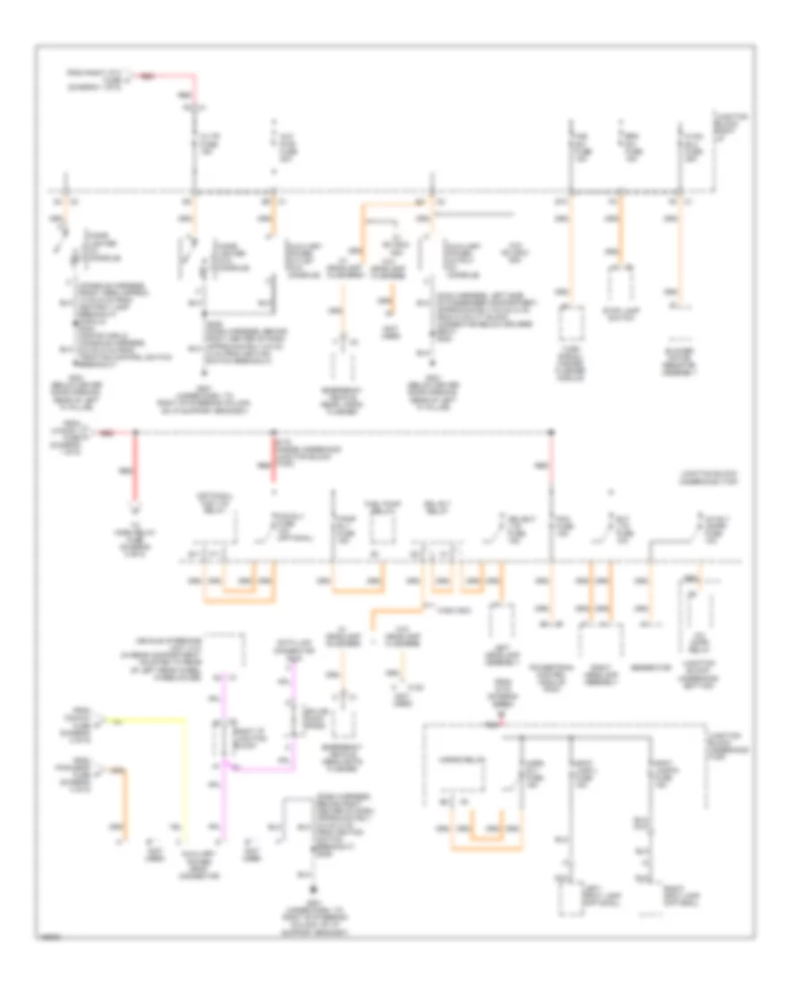
Power Distribution Wiring Diagram (4 of 5) for Chevrolet Impala 2003
 https://portal-diagnostov.com/license.html
Automotive Electricians Portal FZCO
Automotive Electricians Portal FZCO
https://portal-diagnostov.com/license.html
https://portal-diagnostov.com/license.html
Automotive Electricians Portal FZCO
Automotive Electricians Portal FZCOList of elements for Power Distribution Wiring Diagram (4 of 5) for Chevrolet Impala 2003:
- (rear body harness, right side of rear compartment, approximately (19.5 cm) (7 in) from grommet right rear corner of rear compartment) s400
- (roof harness, right side of roof approximately 12.5 cm (5 in) from dome lamp breakout, toward rear of roof) s391
- A11
- A12 c2
- Auxiliary dome lamp
- B/u lp fuse 10a
- Backup lp relay
- Batt rundown protection relay
- Body control module (bcm)
- C1 d4
- C2 e8
- C2 f10
- C311
- C312
- C400
- Connector) s176
- D10
- D9 c2
- Dic/rke fuse 10a
- Dome lamp
- Driver information center (dic)
- Driver seat
- Driver seat adjuster switch
- E3 c1
- E5 c2
- Emergency vehicle rear compartment lid lamps relay
- F1 c1
- F12
- F4 c1
- From junction block- underhood (top) (diagram 1 of 5)
- Front park lp fuse 15a
- Front passenger heated seat relay
- Front passenger seat
- Front passenger seat adjuster switch
- H10
- H11
- H12
- Headlamp switch
- Hvac control module
- I/p brp fuse 10a
- I/p compart- ment lamp
- If equipped
- Impala
- Inside rearview mirror
- Inside rearview mirror (optional)
- Junction block- right i/p
- K10
- K11
- K12
- L10
- Left backup lamp
- Left headlamp assembly
- Left i/p courtesy lamp
- Left license lamp
- Left reading lamp assembly (impala)
- Left tail lamp assembly
- Left vanity mirror lamp (optional)
- License lamp
- Monte carlo
- N10
- Nca
- Park lp relay
- Pwr drop fuse 15a
- Pwr seats circuit breaker 30a
- Rear compart- ment courtesy lamp
- Rear compartment occupant sensor
- Rear prk lp fuse 15a
- Red
- Remote control door lock receiver (rcdlr) (if equipped)
- Rh htd st fuse 15a
- Right backup lamp
- Right headlamp assembly
- Right i/p courtesy lamp
- Right license lamp
- Right reading lamp assembly (impala)
- Right tail lamp assembly
- Right vanity mirror lamp (optional)
- To auxiliary power drop connector (diagram 5 of 5)
- Trk/ roof brp fuse 15a
- Vehicle communication interface module
- W/ gps
- W/o gps
Power Distribution Wiring Diagram (5 of 5) for Chevrolet Impala 2003
 https://portal-diagnostov.com/license.html
Automotive Electricians Portal FZCO
Automotive Electricians Portal FZCO
https://portal-diagnostov.com/license.html
https://portal-diagnostov.com/license.html
Automotive Electricians Portal FZCO
Automotive Electricians Portal FZCOList of elements for Power Distribution Wiring Diagram (5 of 5) for Chevrolet Impala 2003:
- (diagram 1 of 5)
- (not used)
- (optional) fog lts relay
- A/c cmpr relay
- A/c rly (cmpr) fuse 10a
- Approximately 6.5 cm (2 in) from 8 cavity black connector below driver's seat) s320
- Aux pwr fuse 20a
- Auxiliary power drop connector
- Auxiliary power outlet (w/o console)
- Auxiliary power output (w/ console)
- Blower motor resistor assembly
- Brk sw fuse 15a
- C/ltr fuse 15a
- C122
- Cigar lighter (w/ console)
- Cigar lighter (w/o console)
- Data link connector (dlc)
- Drl rly relay
- Drl/ext lts fuse 15a
- E10
- E11
- Emergency vehicle headlights flasher
- Emergency vehicle rear lamps flasher
- Ext lts fuse 10a
- F/pmp rly fuse 15a
- F11
- Fog rly fuse 10a (optional)
- From cig/aux fuse (diagram 2 of 5)
- From ignition switch breakout) s229
- From pwr drop fuse (diagram 4 of 5)
- From right i/p 2 fuse h
- From s178 (diagram 5 of 5)
- From u/hood 1 fuse (diagram 1 of 5)
- Fuel pump relay
- G201 (under dash, to right of steering column, on i/p support bracket)
- G301 (below driver door opening, rear of left "a" pillar)
- Generator
- Haz sw fuse 15a
- Horn rly fuse 15a
- Horns relay
- Hvac blo fuse 25a
- Junction block- right i/p
- Junction block- underhood (bottom)
- Junction block- underhood (top)
- Left headlamp assembly
- Left- spot lamp (optional)
- Nca
- Pcm fuse 15a
- Powertrain control module (pcm)
- Red
- Right headlamp assembly
- Right i/p junction block
- Right- spot lamp (optional)
- S178 (inside underhood junction block (top)) red
- Splice pack- sp205
- Spot lamp-l fuse 15a
- Spot lamp-r fuse 15a
- Stop lamp switch
- To horn relay fuse (diagram 5 of 5)
- Turn signal/ hazard flasher module
- Vehicle interface unit (viu) (in rear compartment, mounted to rear of left rear wheel wheelhouse)
- W/ headlamp flashers
- W/ 9c1/9c3/ 9c8
- W/9c1/9c3
- W/o 9c1/9c3/ 9c8
- W/o headlamp flashers

 Čeština
 Dansk
Dansk Deutsch
 Ελληνικά
 English
 English
 Español
 Suomi
Suomi Français
 Français
 עברית
עברית Hrvatski
 Magyar
 Italiano
 日本語
日本語 한국어
한국어 Nederlands
 Polski
 Português
 Português
 Română
 Русский
 Slovenčina
 Slovenščina
 Svenska
 Türkçe
