AIR CONDITIONING
4.9L
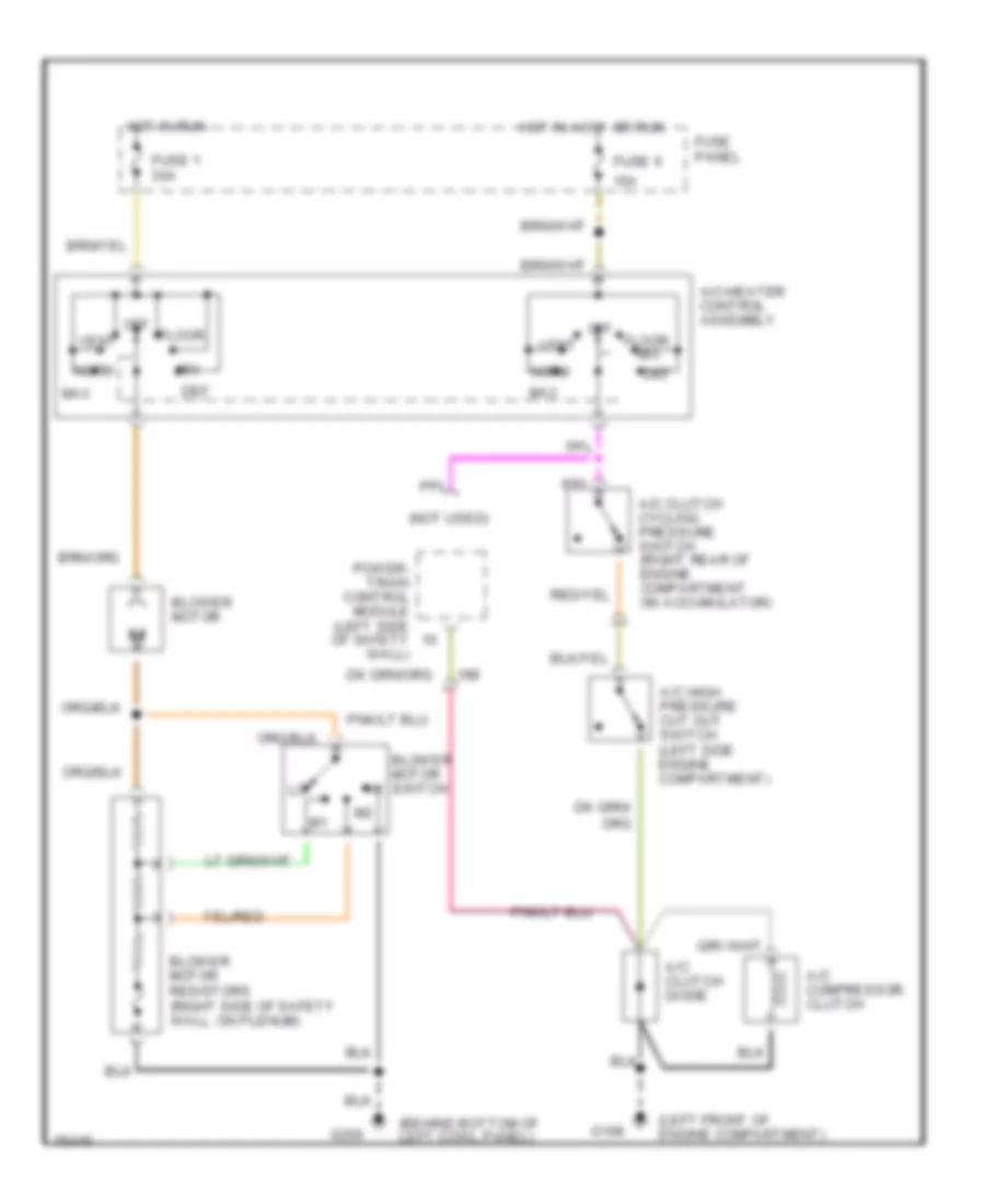
4.9L, A/C Wiring Diagram for Ford Cab & Chassis F350 1996

List of elements for 4.9L, A/C Wiring Diagram for Ford Cab & Chassis F350 1996:
- (behind bottom of left cowl panel)
- (left front of engine compartment)
- (not used)
- 15a
- A/c clutch cycling pressure switch (right rear of engine compartment on accumulator)
- A/c clutch diode
- A/c compressor clutch
- A/c high pressure cut out switch (left side engine compartment)
- A/c-heater control assembly
- Blower motor
- Blower motor resistors (right side of safety wall, on plenum)
- Blower motor switch
- Def
- Floor
- Fuse 1 30a
- Fuse 6
- Fuse panel
- G108
- G200
- Hot in accy or run
- Hot in run
- Max
- Mix
- Norm
- Off
- Pcm power relay
- Power- train control module (left side of safety wall)
- Red
- Vent
- Wac relay (engine compartment fuse box)
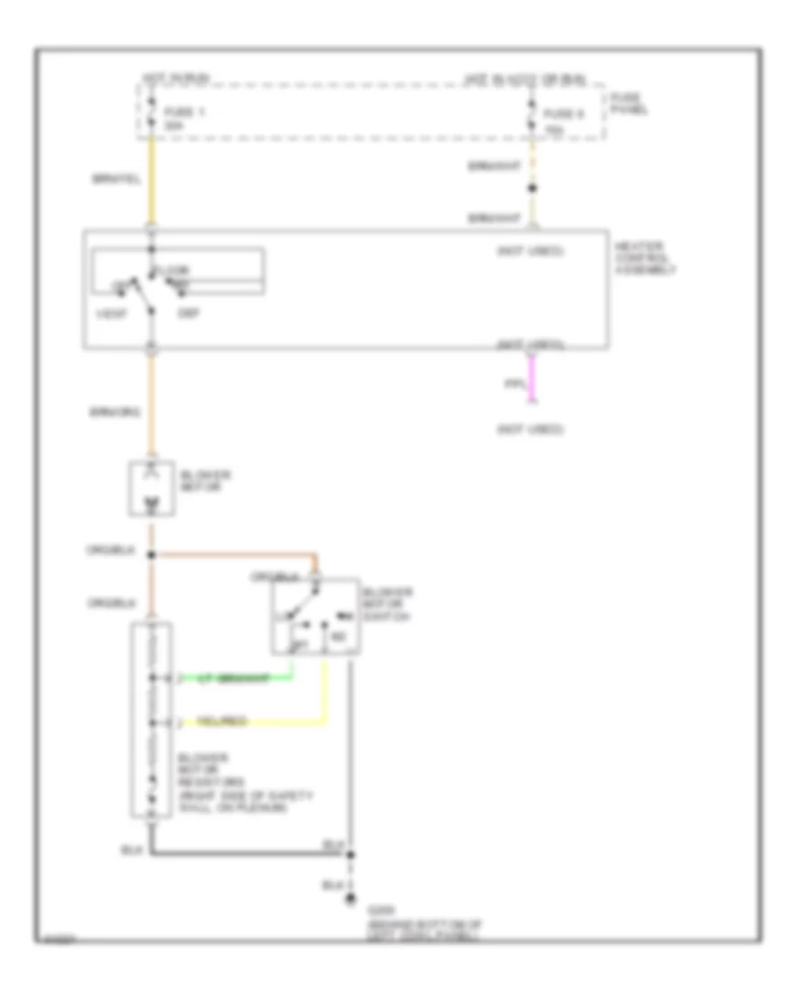
Heater Wiring Diagram for Ford Cab & Chassis F350 1996
List of elements for Heater Wiring Diagram for Ford Cab & Chassis F350 1996:
- (not used)
- 15a
- Blower motor
- Blower motor resistors (right side of safety wall, on plenum)
- Blower motor switch
- Def
- Floor
- Fuse 1 30a
- Fuse 6
- Fuse panel
- G200 (behind bottom of left cowl panel)
- Heater control assembly
- Hot in accy or run
- Hot in run
- Mix
- Off
- Vent
5.8L
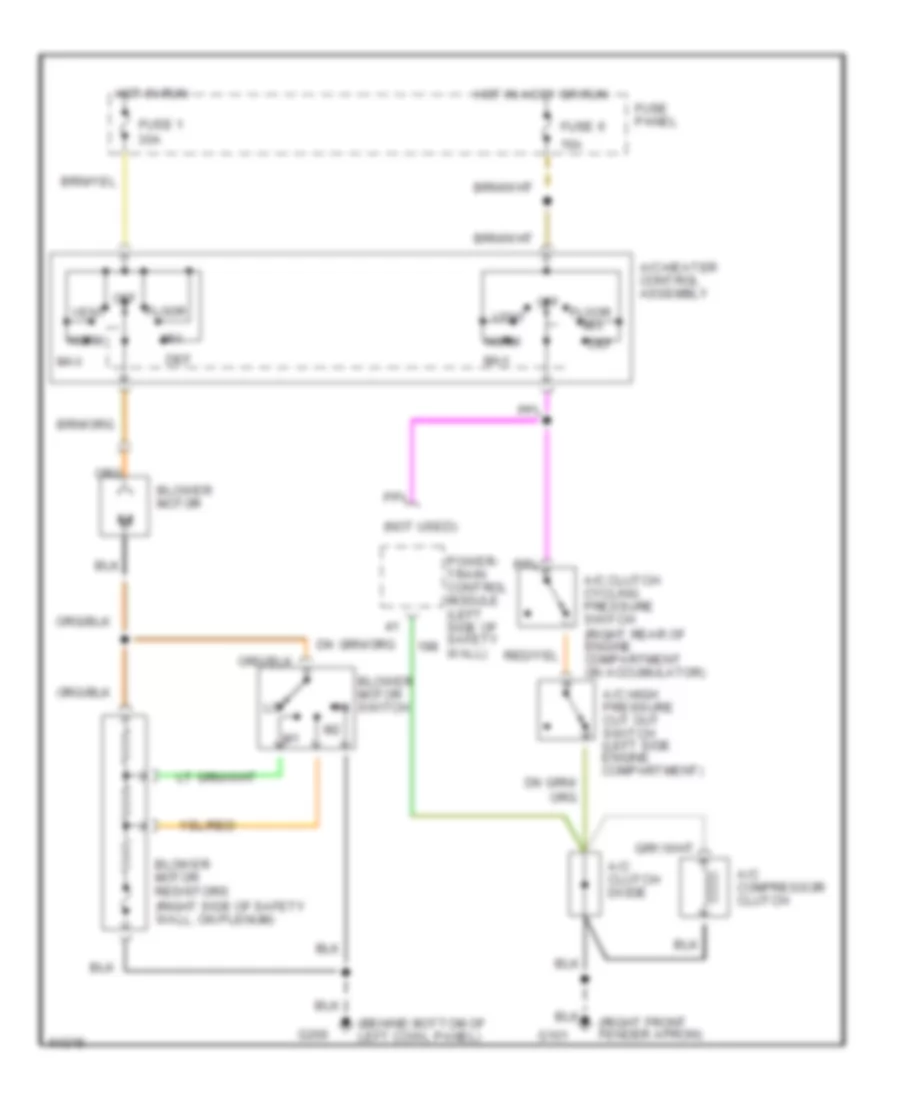
5.8L, A/C Wiring Diagram for Ford Cab & Chassis F350 1996
List of elements for 5.8L, A/C Wiring Diagram for Ford Cab & Chassis F350 1996:
- (behind bottom of left cowl panel)
- (left front of engine compartment)
- (not used)
- 15a
- A/c clutch cycling pressure switch (right rear of engine compartment on accumulator)
- A/c clutch diode
- A/c compressor clutch
- A/c high pressure cut out switch (left side engine compartment)
- A/c-heater control assembly
- Blower motor
- Blower motor resistors (right side of safety wall, on plenum)
- Blower motor switch
- Def
- Floor
- Fuse 1 30a
- Fuse 6
- Fuse panel
- G108
- G200
- Hot in accy or run
- Hot in run
- Max
- Mix
- Norm
- Off
- Power- train control module (left side of safety wall)
- Vent
Heater Wiring Diagram for Ford Cab & Chassis F350 1996
List of elements for Heater Wiring Diagram for Ford Cab & Chassis F350 1996:
- (not used)
- 15a
- Blower motor
- Blower motor resistors (right side of safety wall, on plenum)
- Blower motor switch
- Def
- Floor
- Fuse 1 30a
- Fuse 6
- Fuse panel
- G200 (behind bottom of left cowl panel)
- Heater control assembly
- Hot in accy or run
- Hot in run
- Mix
- Off
- Vent
7.3L
7.3L DI Turbo Diesel, Air Conditioning Wiring Diagrams for Ford Cab & Chassis F350 1996
List of elements for 7.3L DI Turbo Diesel, Air Conditioning Wiring Diagrams for Ford Cab & Chassis F350 1996:
- (behind bottom of left cowl panel)
- (not used)
- (right front fender apron)
- 15a
- A/c clutch cycling pressure switch (right rear of engine compartment on accumulator)
- A/c clutch diode
- A/c compressor clutch
- A/c high pressure cut out switch (left side engine compartment)
- A/c-heater control assembly
- Blower motor
- Blower motor resistors (right side of safety wall, on plenum)
- Blower motor switch
- Def
- Floor
- Fuse 1 30a
- Fuse 6
- Fuse panel
- G101
- G200
- Hot in accy or run
- Hot in run
- Max
- Mix
- Norm
- Off
- Power- train control module (left side of safety wall)
- Vent
Heater Wiring Diagram for Ford Cab & Chassis F350 1996
List of elements for Heater Wiring Diagram for Ford Cab & Chassis F350 1996:
- (not used)
- 15a
- Blower motor
- Blower motor resistors (right side of safety wall, on plenum)
- Blower motor switch
- Def
- Floor
- Fuse 1 30a
- Fuse 6
- Fuse panel
- G200 (behind bottom of left cowl panel)
- Heater control assembly
- Hot in accy or run
- Hot in run
- Mix
- Off
- Vent
7.5L
7.5L, A/C Wiring Diagram for Ford Cab & Chassis F350 1996
List of elements for 7.5L, A/C Wiring Diagram for Ford Cab & Chassis F350 1996:
- (behind bottom of left cowl panel)
- (left front of engine compartment)
- (not used)
- 15a
- A/c clutch cycling pressure switch (right rear of engine compartment on accumulator)
- A/c clutch diode
- A/c compressor clutch
- A/c high pressure cut out switch (left side engine compartment)
- A/c-heater control assembly
- Blower motor
- Blower motor resistors (right side of safety wall, on plenum)
- Blower motor switch
- Def
- Floor
- Fuse 1 30a
- Fuse 6
- Fuse panel
- G108
- G200
- Hot in accy or run
- Hot in run
- Max
- Mix
- Norm
- Off
- Power- train control module (left side of safety wall)
- Vent
Heater Wiring Diagram for Ford Cab & Chassis F350 1996
List of elements for Heater Wiring Diagram for Ford Cab & Chassis F350 1996:
- (not used)
- 15a
- Blower motor
- Blower motor resistors (right side of safety wall, on plenum)
- Blower motor switch
- Def
- Floor
- Fuse 1 30a
- Fuse 6
- Fuse panel
- G200 (behind bottom of left cowl panel)
- Heater control assembly
- Hot in accy or run
- Hot in run
- Mix
- Off
- Vent