ENGINE PERFORMANCE
4.9L
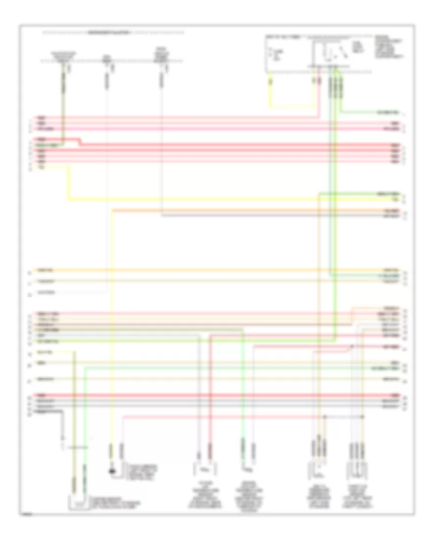
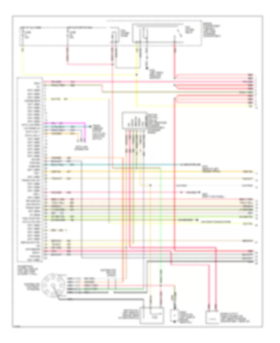
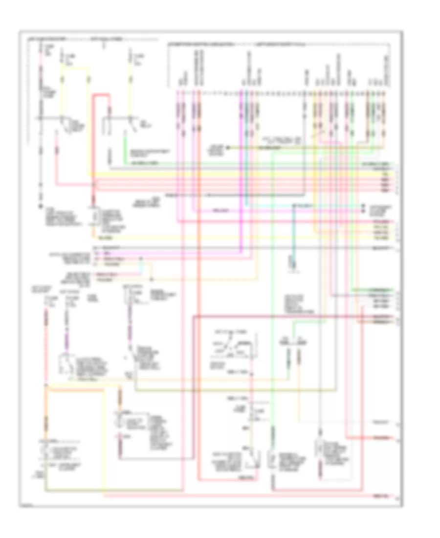
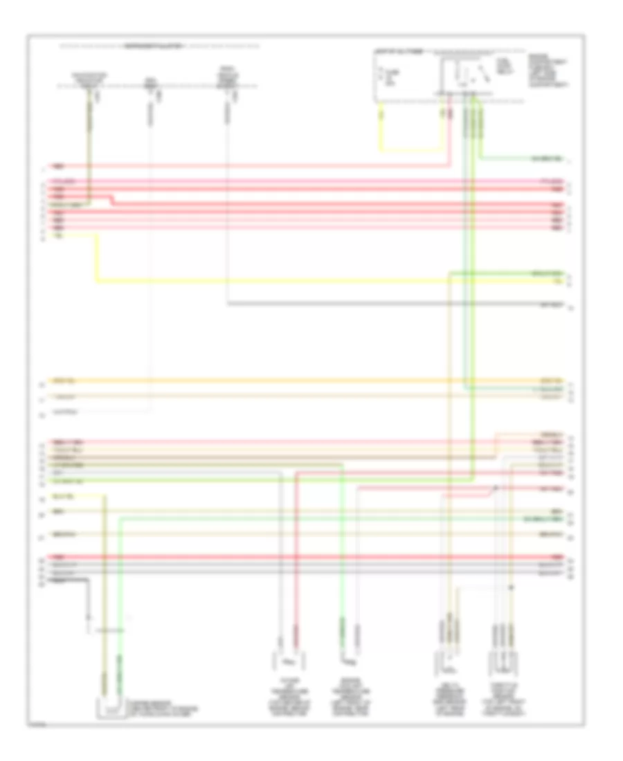
4.9L, Engine Performance Wiring Diagrams (1 of 4) for Ford Cab & Chassis F350 1996

List of elements for 4.9L, Engine Performance Wiring Diagrams (1 of 4) for Ford Cab & Chassis F350 1996:
- (4x4 hi/low indicator switch)
- (not used)
- A/c clutch sig
- Air conditioning system
- Aird solnd
- Case gnd
- Ckp sensor
- Coil
- Data link (+)
- Data link (-)
- Data link connector
- Data link feps
- Distributor (left front of engine)
- Distributor ignition shield
- Ect sens
- Egr solnd ctrl
- Engine compartment fuse box (left side of engine compartment)
- Fuel pump mon
- Fuse 20a
- Fuse 30a
- G104 (rear of left fender apron)
- G108 (left front radiator support)
- G203 (right kick panel)
- Ho2s 12 sig
- Hot at all times
- Hot in start or run
- Iat sens
- Idm
- Idm (fto)
- Ign gnd
- Ignition coil (left front of engine, forward of distributor)
- Ignition control module (left rear side of engine compartment, on fender apron)
- Low rnge 4x4
- Maf sig rtn
- Mil
- Misfire sens
- Nca
- Pcm power diode
- Pcm power relay
- Pip
- Pnk
- Power
- Powertrain control module (top left side of safety wall)
- Pwr gnd
- Pwr grd
- Radio capacitor (left front of engine, near coil)
- Red
- Red/
- Spark output check connector (left rear of engine compartment, near icm)
- Spout
- Trans ctrl sw
- Trans temp
- Trans- missions system
- Tss 1
- Tss 2
- Vss (-)
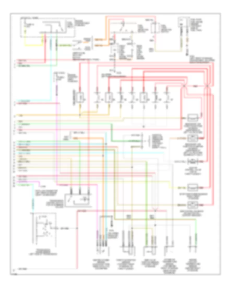
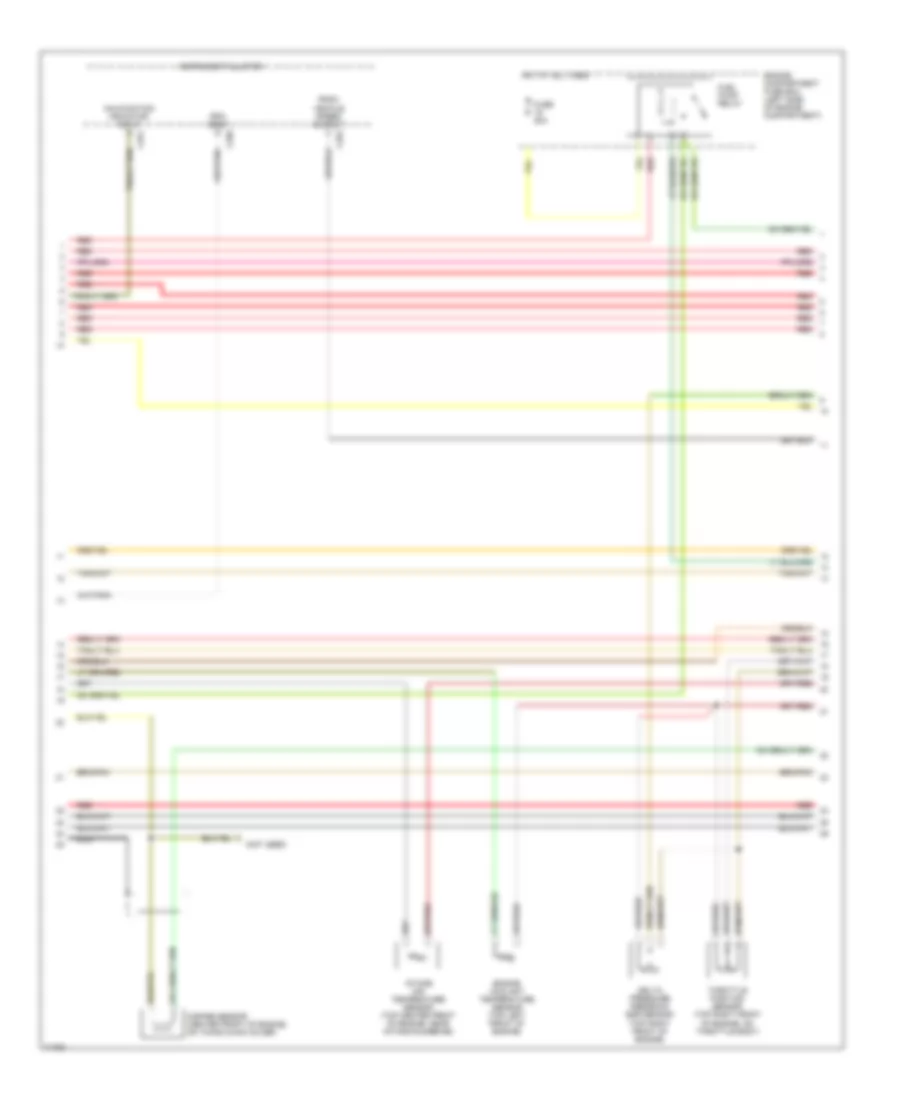
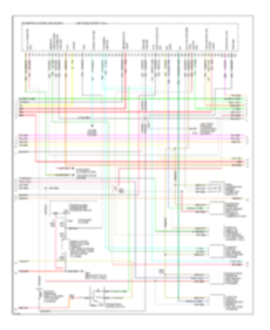
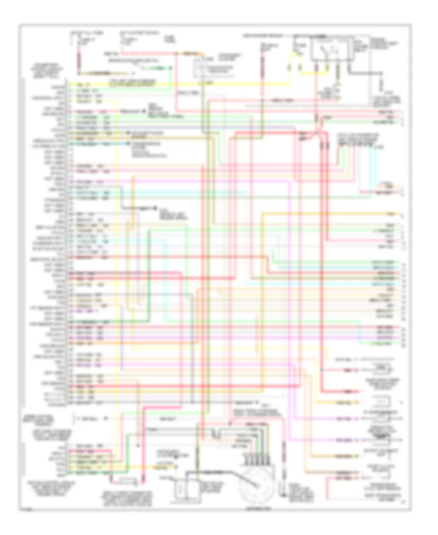
4.9L, Engine Performance Wiring Diagrams (2 of 4) for Ford Cab & Chassis F350 1996
List of elements for 4.9L, Engine Performance Wiring Diagrams (2 of 4) for Ford Cab & Chassis F350 1996:
- C250
- C251
- C252
- Delta pressure feedback egr sensor (left side of engine)
- Engine compartment fuse box (left side of engine compartment)
- Engine coolant temperature sensor (center front of engine, on thermostat housing)
- Fuel pump relay
- Fuse 20a
- Hot at all times
- Instrument cluster
- Intake air temperature sensor (right front of engine, near intake runner #1)
- Knock sensor (left front of engine, near ignition coil)
- Malfunction indicator input
- Misfire sensor (center front of engine, on timing chain cover)
- Nca
- Psom vehicle speed output
- Red
- Rpm input
- Throttle position sensor (top left rear of engine, on throttle body)
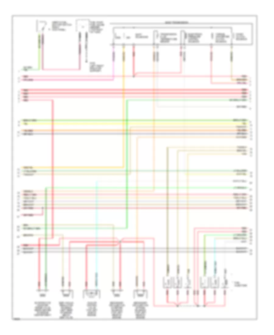
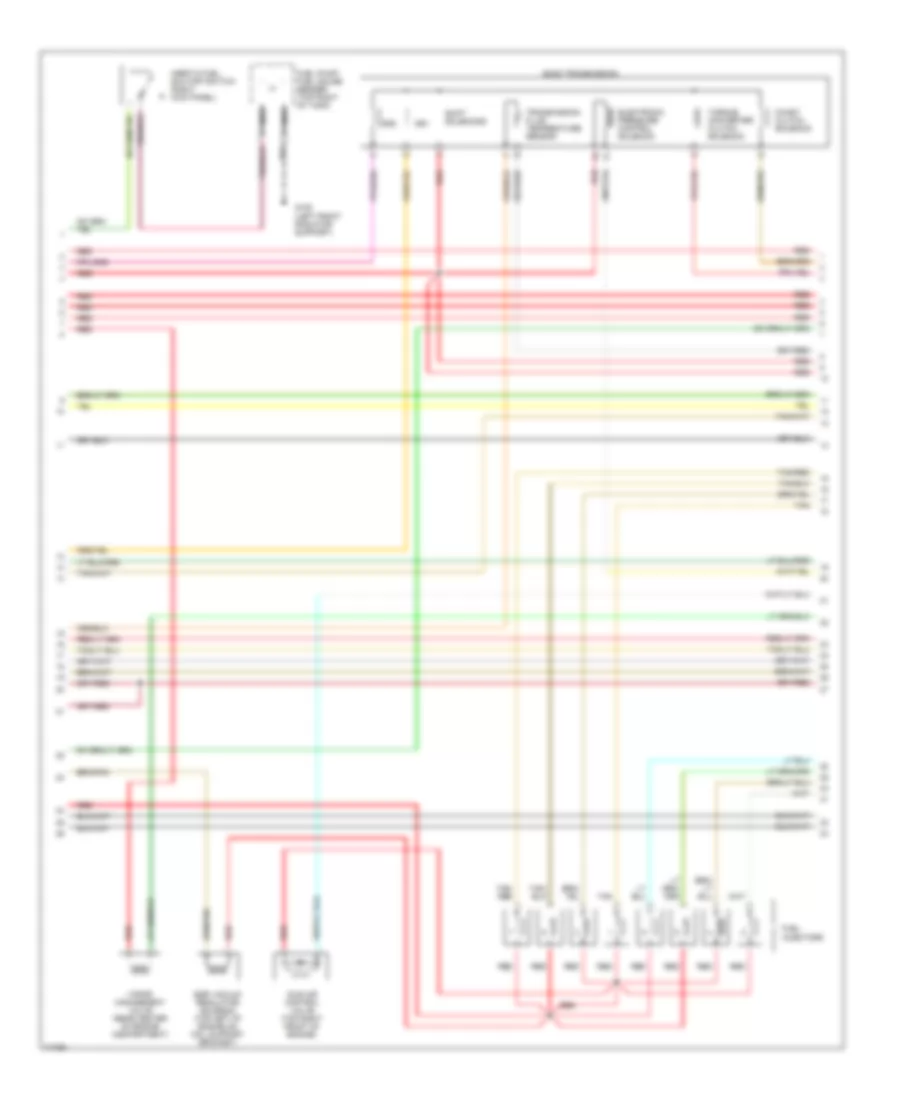
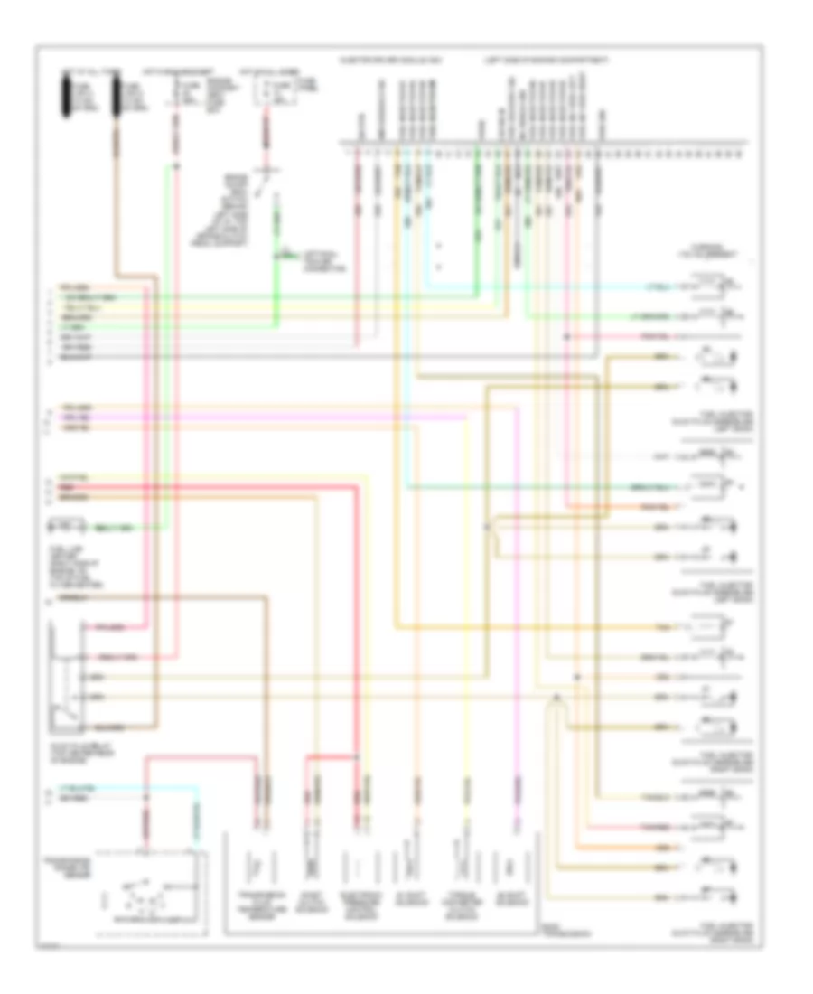
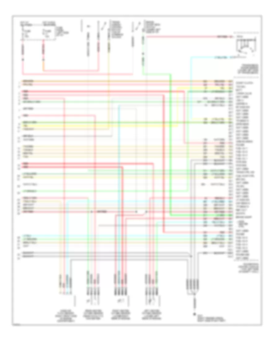
4.9L, Engine Performance Wiring Diagrams (3 of 4) for Ford Cab & Chassis F350 1996
List of elements for 4.9L, Engine Performance Wiring Diagrams (3 of 4) for Ford Cab & Chassis F350 1996:
- Coast clutch solenoid
- E4od transmission
- Egr vacuum regulator solenoid (left rear of engine, below egr valve)
- Electronic pressure control solenoid
- Evaporative canister purge valve (rear center of engine compartment)
- Fuel injectors
- Fuel pump/ fuel gauge sender (top right of tank)
- G108 (left front radiator support)
- Idle air control valve (top left side of engine)
- Inertia fuel shutoff switch (right kick panel)
- Nca
- Red
- Secondary air injection bypass solenoid (top left rear of engine)
- Secondary air injection diverter solenoid (top left rear of engine)
- Shift solenoids
- Ss1
- Ss2
- Tan
- Torque converter clutch solenoid
- Transmission fluid temperature sensor
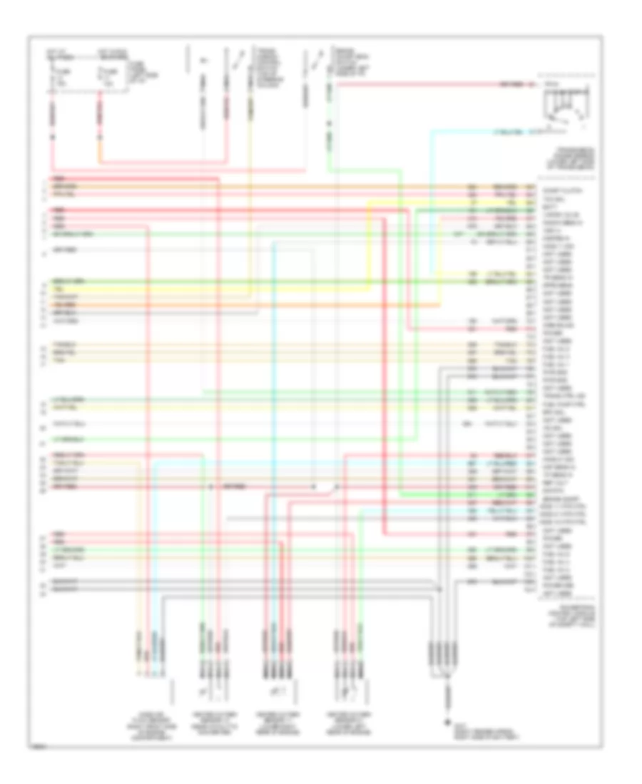
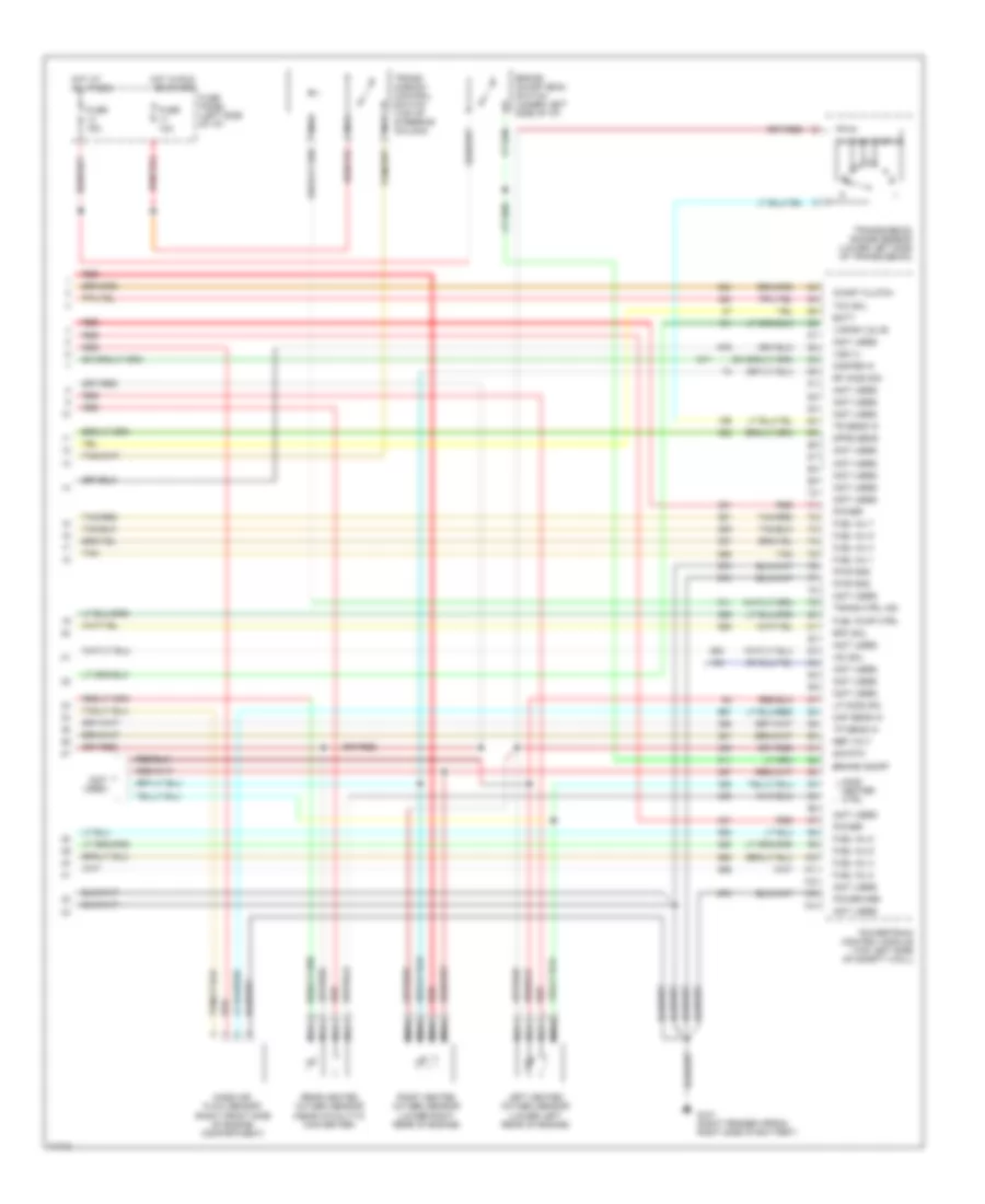
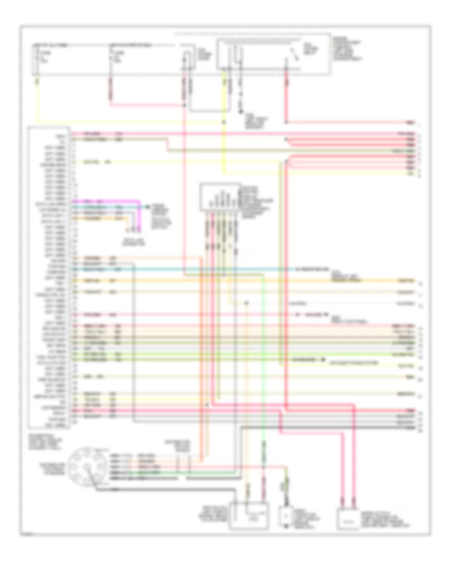
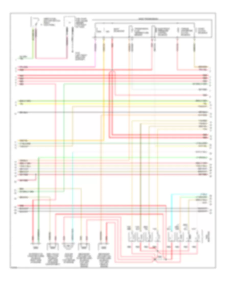
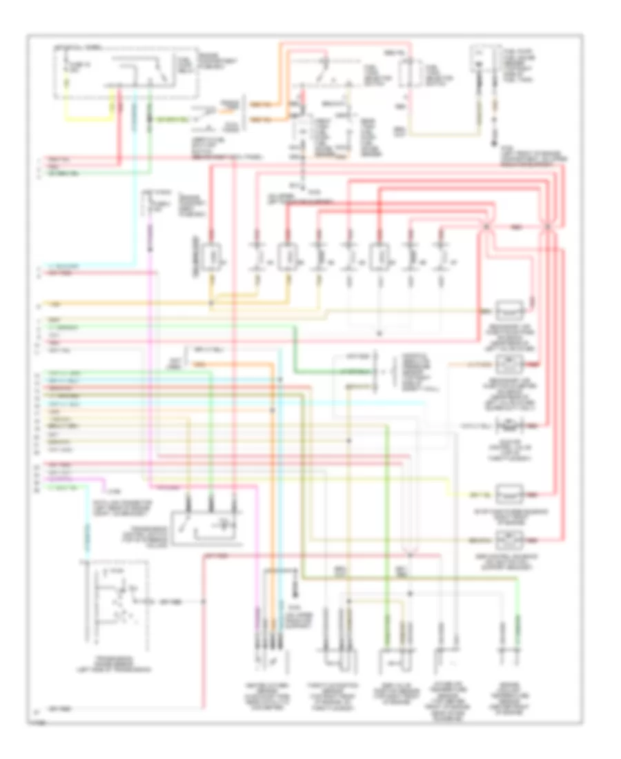
4.9L, Engine Performance Wiring Diagrams (4 of 4) for Ford Cab & Chassis F350 1996
List of elements for 4.9L, Engine Performance Wiring Diagrams (4 of 4) for Ford Cab & Chassis F350 1996:
- (not used)
- Airb solnd
- Batt
- Brake on/off
- Brake on/off (boo) switch (under left side of i/p)
- Coast clutch
- Dpfe sens
- Epc sol
- Fuel inj 1
- Fuel inj 2
- Fuel inj 3
- Fuel inj 4
- Fuel inj 5
- Fuel inj 6
- Fuel pump ctrl
- Fuse 10a
- Fuse 15a
- Fuse panel (left side of i/p)
- G101 (right fender apron, right side of battery)
- H02s 11 htr ctrl
- H02s 12 htr ctrl
- H02s 21 htr ctrl
- Heated oxygen sensor 11 (lower right rear of engine)
- Heated oxygen sensor 12 (near catalytic converter)
- Heated oxygen sensor 21 (lower left rear of engine)
- Ho2s 11 sig
- Ho2s 21 sig
- Hot at all times
- Hot in run or start
- Iac sol
- Knock sens in
- Maf sens in
- Mass air flow sensor (right front side of engine compartment)
- Misfire in
- Nca
- Power
- Power gnd
- Powertrain control module (top left side of safety wall)
- Pwr gnd
- Red
- Ref volt
- Sig rtn
- Tan
- Tcc sol
- Tp sens in
- Tr sens in
- Trans ctrl ind
- Trans- mission control switch (top of steering column)
- Transmission range sensor (lower left side of transmission)
- Vapor valve
- Vss (+)
5.8L
5.8L, Engine Performance Wiring Diagrams, Over 8500 GVWR (1 of 2) for Ford Cab & Chassis F350 1996
List of elements for 5.8L, Engine Performance Wiring Diagrams, Over 8500 GVWR (1 of 2) for Ford Cab & Chassis F350 1996:
- #1 shift solenoid
- #2 shift solenoid
- (4x4 hi/lo indicator switch)
- (left side of engine compt., near brake master cylinder)
- (not used)
- (right front of engine compt, on fender apron)
- (top left side of brake/ clutch pedal support)
- (top of upper left radiator support)
- Accs
- Air conditioning system
- Airb solnd ctrl
- Aird solnd ctrl
- Boo
- Brake on/off (boo) switch
- C198
- C250
- C251
- Ccs
- Ckp sensor
- Coast clutch solenoid
- Coil
- Coil wire
- Cse gnd
- Data link connector (left rear of engine compt, on bracket)
- Distributor
- E40d transmission
- Ect
- Egr cntrl solnd.
- Egr valve pos
- Electronic pres- sure control solenoid
- Engine compartment fuse box
- Epc
- Evap can solnd.
- Fp enable
- Fpm
- Fuse 13 15a
- Fuse 17 10a
- Fuse 20a
- Fuse 22 20a
- Fuse panel
- G101
- G104 (rear of left fender apron)
- G108
- G203 (behind bottom of right cowl panel)
- Gnd
- Ho2s ground
- Ho2s sig input
- Hot at all times
- Hot in start or run
- Iac
- Iat
- Idm
- Idm (fto)
- Ign gnd
- Ignition coil (left rear of engine)
- Ignition control module (left rear of engine compartment, on fender apron)
- Inj 1, 4, 5, 8
- Inj 2, 3, 6, 7
- Instrument cluster
- Instrument cluster system
- Kapwr
- Low rnge 4x4 ind
- Malfunction indicator
- Map sensor input
- Nca
- Pcm power diode
- Pcm power relay
- Pip
- Pnk
- Powertrain control module (left side of safety wall)
- Pwr
- Pwr gnd
- Radio capacitor (left side of engine, near ignition coil)
- Red
- Sig rtn
- Speed control servo/amplifier assembly
- Spout
- Spout check connector (left rear of engine compt, taped to harness, near ignition control module)
- Sto/mil
- Tan
- Tcc
- Tcil
- Tcs
- Tft sensor input
- Torque con- verter clutch solenoid
- Tps input
- Tr sensor input
- Transmission fluid temp sensor
- Transmissions system
- Tss 1
- Tss 2
- Vip dlc
- Vpwr
- Vref
- Vss ground
- Vss signal input
5.8L, Engine Performance Wiring Diagrams, Over 8500 GVWR (2 of 2) for Ford Cab & Chassis F350 1996
List of elements for 5.8L, Engine Performance Wiring Diagrams, Over 8500 GVWR (2 of 2) for Ford Cab & Chassis F350 1996:
- (not used)
- (on upper left radiator support)
- (on upper radiator support)
- C199
- Data link connector (left rear of engine compt, on bracket)
- Dual tanks
- Egr control solenoid (on ignition coil support bracket)
- Egr valve position sensor (top right front of engine)
- Engine compart- ment fuse box
- Engine compartment fuse box
- Engine coolant temperature sensor (center front of engine)
- Evap cann purge solenoid (right front of engine)
- Front tank fuel pump/ fuel gauge sender
- Fuel injectors
- Fuel pump relay
- Fuel pump/ fuel gauge sender (top right side of fuel tank)
- Fuel tank selector switch
- Fuse 16 20a
- Fuse 5 15a
- G108
- G108 (left front of engine compartment, on upper radiator support)
- Heated oxygen sensor (in exhaust pipe, near catalytic converter)
- Hot at all times
- Hot in run
- Idle air control valve (top of throttle body)
- Inertia fuel shut-off switch (behind right cowl panel)
- Intake air temperature sensor (top center front of engine, near intake runner #6)
- Manifold absolute pressure sensor (top right side of safety wall)
- Nca
- Rear tank fuel pump/ fuel gauge sender
- Red
- Secondary air injection bypass solenoid (near rear of left valve cover)
- Secondary air injection diverter solenoid (near rear of left valve cover) (super duty only)
- Single tank
- Tan
- Tcil
- Throttle position sensor (top right front of engine, on throttle body)
- Transmission control switch (top of steering column)
- Transmission range sensor (left side of transmission)
5.8L, Engine Performance Wiring Diagrams, Under 8500 GVWR (1 of 4) for Ford Cab & Chassis F350 1996
List of elements for 5.8L, Engine Performance Wiring Diagrams, Under 8500 GVWR (1 of 4) for Ford Cab & Chassis F350 1996:
- (not used)
- A/c clutch sig
- Air conditioning system
- Case gnd
- Ckp sensor
- Coil
- Data link (+)
- Data link (-)
- Data link connector
- Data link feps
- Distributor (top front of engine)
- Distributor ignition shield
- Ect sens
- Egr solnd ctrl
- Engine compartment fuse box (left side of engine compartment)
- Fuel pump mon
- Fuse 20a
- Fuse 30a
- G104 (rear of left fender apron)
- G108 (left front radiator support)
- G203 (right kick panel)
- Hot at all times
- Hot in start or run
- Iat sens
- Idm
- Idm (fto)
- Ign gnd
- Ignition coil (left rear of engine, near intake manifold)
- Ignition control module (left rear side of engine compartment, on fender apron)
- Low rnge 4x4
- Maf sig rtn
- Mil
- Misfire sens
- Nca
- Pcm power diode
- Pcm power relay
- Pip
- Pnk
- Power
- Powertrain control module (top left side of safety wall)
- Pwr gnd
- Pwr grd
- Radio capacitor (left side of engine, near coil)
- Red
- Red/
- Rr ho2s sig
- Spark output check connector (left rear of engine compartment, near icm)
- Spout
- Trans ctrl sw
- Trans temp
- Trans- missions system (4x4 hi/low indicator switch)
- Tss 1
- Tss 2
- Vss (-)
5.8L, Engine Performance Wiring Diagrams, Under 8500 GVWR (2 of 4) for Ford Cab & Chassis F350 1996
List of elements for 5.8L, Engine Performance Wiring Diagrams, Under 8500 GVWR (2 of 4) for Ford Cab & Chassis F350 1996:
- (not used)
- C250
- C251
- C252
- Delta pressure feedback egr sensor (top right front of engine)
- Engine compartment fuse box (left side of engine compartment)
- Engine coolant temperature sensor (top left front of engine)
- Fuel pump relay
- Fuse 20a
- Hot at all times
- Instrument cluster
- Intake air temperature sensor (top center front of engine, near intake runner #6)
- Malfunction indicator input
- Misfire sensor (center front of engine, on timing chain cover)
- Nca
- Psom vehicle speed output
- Red
- Rpm input
- Throttle position sensor (top right front of engine, on throttle body)
5.8L, Engine Performance Wiring Diagrams, Under 8500 GVWR (3 of 4) for Ford Cab & Chassis F350 1996
List of elements for 5.8L, Engine Performance Wiring Diagrams, Under 8500 GVWR (3 of 4) for Ford Cab & Chassis F350 1996:
- Coast clutch solenoid
- E4od transmission
- Egr vacuum regulator solenoid (top left of engine on coil support bracket)
- Electronic pressure control solenoid
- Fuel injectors
- Fuel pump/ fuel gauge sender (top right of tank)
- G108 (left front radiator support)
- Idle air control valve (top right front of engine)
- Inertia fuel shutoff switch (right kick panel)
- Nca
- Red
- Shift solenoids
- Ss1
- Ss2
- Tan
- Tan/ red
- Tan/red
- Torque converter clutch solenoid
- Transmission fluid temperature sensor
- Vapor management valve (rear center of engine compartment)
5.8L, Engine Performance Wiring Diagrams, Under 8500 GVWR (4 of 4) for Ford Cab & Chassis F350 1996
List of elements for 5.8L, Engine Performance Wiring Diagrams, Under 8500 GVWR (4 of 4) for Ford Cab & Chassis F350 1996:
- (not used)
- Batt
- Brake on/off
- Brake on/off (boo) switch (under left side of i/p)
- Coast clutch
- Dpfe sens
- Epc sol
- Fuel inj 1
- Fuel inj 2
- Fuel inj 3
- Fuel inj 4
- Fuel inj 5
- Fuel inj 6
- Fuel inj 7
- Fuel inj 8
- Fuel pump ctrl
- Fuse 10a
- Fuse 15a
- Fuse panel (left side of i/p)
- G101 (right fender apron, right side of battery)
- H02s heater ctrl
- Hot at all times
- Hot in run or start
- Iac sol
- Left heated oxygen sensor (lower left rear of engine)
- Lf ho2s sig
- Maf sens in
- Mass air flow sensor (right front side of engine compartment)
- Misfire in
- Nca
- Power
- Power gnd
- Powertrain control module (top left side of safety wall)
- Pwr gnd
- Rear heated oxygen sensor (near catalytic converter)
- Red
- Ref volt
- Rf ho2s sig
- Right heated oxygen sensor (lower right rear of engine)
- Sig rtn
- Tan
- Tan/red
- Tcc sol
- Tp sens in
- Tr sens in
- Trans ctrl ind
- Trans- mission control switch (top of steering column)
- Transmission range sensor (lower left side of transmission)
- Vapor valve
- Vss (+)
7.3L
7.3L DI Turbo Diesel, Engine Performance Wiring Diagrams (1 of 3) for Ford Cab & Chassis F350 1996
List of elements for 7.3L DI Turbo Diesel, Engine Performance Wiring Diagrams (1 of 3) for Ford Cab & Chassis F350 1996:
- "wait to start" indicator
- (a/t)
- (left side of safety wall)
- (m/t)
- 4x4 hi/low indicator switch (front of transfer case)
- Acc
- Brake press sw
- Brake warning ind
- C250
- C251
- C264
- Clutch pedal position switch (top right side of brake/clutch pedal support)
- Cruise control system
- Data link connector (behind lower center of i/p)
- Diesel warning lamps display (top left side of i/p, right of instrument cluster)
- Dlc
- Ebp
- Engine compartment fuse box
- Engine oil temperature (eot) sensor (front top of engine)
- Eot
- Fuse 10a
- Fuse 15a
- Fuse 20a
- Fuse 30a
- Fuse 3a
- Fuse panel
- G104 (rear of left fender apron)
- G108 (left front of engine compart- ment, on upper radiator support)
- Hot at all times
- Hot in run
- Hot in run or start
- Iat
- Idle validation sw
- Idle validation switch (closed at idle) (near accele- rator pedal)
- Idm relay
- Ignition switch
- Injection pressure regulator (ipr) (top center of engine)
- Instrument cluster
- Instrument cluster system
- Intake air temper- ature (iat) sensor (top center of engine)
- Lock
- Low range 4x4 sw
- Malfunction indicator lamp (mil)
- Map
- Off
- Pcm dlc
- Pcm power relay
- Power diode
- Powertrain control module (pcm)
- Pwr gnd
- Red
- Rpm ctrl
- Run
- Selectable rpm control (behind center of i/p)
- Speed ctrl gnd
- Ss1
- Ss2
- Start
- Tcc
- Tcs or cpp
- Tft
- Vss gnd
- W/ e4od
- W/o e4od
7.3L DI Turbo Diesel, Engine Performance Wiring Diagrams (2 of 3) for Ford Cab & Chassis F350 1996
List of elements for 7.3L DI Turbo Diesel, Engine Performance Wiring Diagrams (2 of 3) for Ford Cab & Chassis F350 1996:
- (left front of engine compartment, on radiator support)
- (left side of safety wall)
- A/c cyl press sw
- Accl pdl pos sens
- Air conditioning system
- Baro
- Barometric pressure (baro) sensor (below i/p, at base of steering column)
- Boo
- C252
- Cam pos sens
- Camshaft position (cmp) sensor (front center of engine)
- Ccs
- Cid sig
- Cmp rtn
- Cruise control system
- Epc
- Epr
- Exhaust back pressure (ebp) sensor (right side of engine)
- Exhaust pressure regulator (epr) (top center of engine)
- Fuel delivery sig
- G108
- G203 (behind bottom of right cowl panel)
- Glow plug ctrl
- Gnd
- Icp
- Idm enable out
- Idm sig in
- Injection control pressure (icp) sensor (top left side of engine)
- Instrument cluster
- Instrument cluster system
- Ipr
- Kapwr
- Manifold absolute pressure (map) sensor (top right side of safety wall)
- Nca
- Pedal accelerator sensor (under left side of i/p)
- Powertrain control module (pcm)
- Programmable speedometer/ odometer module
- Pwr gnd
- Red
- Sig rtn
- Speed control servo/amplifier assembly (left side of engine compartment, near brake master cylinder)
- Speed ctrl gnd
- Tachometer
- Tcil
- Tcs
- Tr sensor
- Transmission control switch
- Vpwr
- Vref
- Vss
- Vss out
- Wait to start out
7.3L DI Turbo Diesel, Engine Performance Wiring Diagrams (3 of 3) for Ford Cab & Chassis F350 1996
List of elements for 7.3L DI Turbo Diesel, Engine Performance Wiring Diagrams (3 of 3) for Ford Cab & Chassis F350 1996:
- #1 shift solenoid
- #2 shift solenoid
- (left side of engine compartment)
- (optional trailer connector)
- Brake on/off (boo) switch (behind left side of i/p, top left side of brake/clutch pedal support)
- Cid sig in
- Coast clutch solenoid
- E4od transmission
- Electronic pressure control solenoid
- Engine compart- ment fuse box
- Fuel delivery sig
- Fuel inj feed left
- Fuel inj feed right
- Fuel injector #1
- Fuel injector #2
- Fuel injector #3
- Fuel injector #4
- Fuel injector #5
- Fuel injector #6
- Fuel injector #7
- Fuel injector #8 fuel injector #1
- Fuel injector/ glow plug assemblies (left bank)
- Fuel injector/ glow plug assemblies (right bank)
- Fuel line heater (right side of engine, on top of fuel filter/heater)
- Fuse 15a
- Fuse 30a
- Fuse panel
- Glow plug relay (top center rear of engine)
- Hot at all times
- Hot in run or start
- Idm feedback sig
- Inj shield gnd
- Injector driver module (idm)
- Nca
- Pwr gnd
- Red
- Sig rtn
- Tan
- Tan/red
- Torque converter clutch solenoid
- Transmission fluid temperature sensor
- Transmission range (tr) sensor
- Vpwr
- Warning: 115v dc present
7.5L
7.5L, Engine Performance Wiring Diagrams, California (1 of 4) for Ford Cab & Chassis F350 1996
List of elements for 7.5L, Engine Performance Wiring Diagrams, California (1 of 4) for Ford Cab & Chassis F350 1996:
- (4x4 hi/lo indicator switch)
- (not used)
- A/c clutch sig
- Air conditioning system
- Aird solenoid
- Case gnd
- Ckp sensor
- Coil
- Data link (+)
- Data link (-)
- Data link connector
- Data link feps
- Distributor (top front of engine)
- Distributor ignition shield
- Ect sens
- Egr solnd ctrl
- Engine compartment fuse box (left side of engine compartment)
- Fuel pump mon
- Fuse 20a
- Fuse 30a
- G104 (rear of left fender apron)
- G108 (left front radiator support)
- G203 (right kick panel)
- Hot at all times
- Hot in start or run
- Iat sens
- Idm
- Idm (fto)
- Ign gnd
- Ignition coil (left side of engine, above valve cover)
- Ignition control module (left rear side of engine compartment, on fender apron)
- Low rnge 4x4
- Maf sig rtn
- Mil
- Misfire sens
- Nca
- Pcm power diode
- Pcm power relay
- Pip
- Pnk
- Power
- Powertrain control module (top left side of safety wall)
- Pwr gnd
- Pwr grd
- Radio capacitor (left side of engine, near coil)
- Red
- Red/
- Rr ho2s sig
- Spark output check connector (left rear of engine compartment, near icm)
- Spout
- Trans ctrl sw
- Trans temp
- Trans- missions system
- Tss 1
- Tss 2
- Vss (-)
7.5L, Engine Performance Wiring Diagrams, California (2 of 4) for Ford Cab & Chassis F350 1996
List of elements for 7.5L, Engine Performance Wiring Diagrams, California (2 of 4) for Ford Cab & Chassis F350 1996:
- C250
- C251
- C252
- Delta pressure feedback egr sensor (left rear of engine)
- Engine compartment fuse box (left side of engine compartment)
- Engine coolant temperature sensor (left front of engine, near distributor)
- Fuel pump relay
- Fuse 20a
- Hot at all times
- Instrument cluster
- Intake air temperature sensor (top center of engine, behind distributor)
- Malfunction indicator input
- Misfire sensor (center front of engine, on timing chain cover)
- Nca
- Psom vehicle speed output
- Red
- Rpm input
- Throttle position sensor (top left front of engine, on throttle body)
7.5L, Engine Performance Wiring Diagrams, California (3 of 4) for Ford Cab & Chassis F350 1996
List of elements for 7.5L, Engine Performance Wiring Diagrams, California (3 of 4) for Ford Cab & Chassis F350 1996:
- Coast clutch solenoid
- E4od transmission
- Egr vacuum regulator solenoid (left side of engine compartment)
- Electronic pressure control solenoid
- Evaporative canister purge solenoid (right side of engine)
- Fuel pump/ fuel gauge sender (top right of tank)
- G108 (left front radiator support)
- Idle air control valve (top center of engine)
- Inertia fuel shutoff switch (right kick panel)
- Injectors fuel
- Nca
- Red
- Secondary air injection bypass (airb) solenoid (top left rear of engine)
- Secondary air injection diverter (aird) solenoid (top left rear of engine)
- Shift solenoids
- Ss1
- Ss2
- Tan
- Tan/ red
- Tan/red
- Torque converter clutch solenoid
- Transmission fluid temperature sensor
7.5L, Engine Performance Wiring Diagrams, California (4 of 4) for Ford Cab & Chassis F350 1996
List of elements for 7.5L, Engine Performance Wiring Diagrams, California (4 of 4) for Ford Cab & Chassis F350 1996:
- (not used)
- Airb solenoid
- Batt
- Brake on/off
- Brake on/off (boo) switch (under left side of i/p)
- Coast clutch
- Dpfe sens
- Epc sol
- Fuel inj 1
- Fuel inj 2
- Fuel inj 3
- Fuel inj 4
- Fuel inj 5
- Fuel inj 6
- Fuel inj 7
- Fuel inj 8
- Fuel pump ctrl
- Fuse 10a
- Fuse 15a
- Fuse panel (left side of i/p)
- G101 (right fender apron, right side of battery)
- H02s heater ctrl
- Hot at all times
- Hot in run or start
- Iac sol
- Left heated oxygen sensor (lower left rear of engine)
- Lf ho2s sig
- Maf sens in
- Mass air flow sensor (right front side of engine compartment)
- Misfire in
- Nca
- Power
- Power gnd
- Powertrain control module (top left side of safety wall)
- Pwr gnd
- Rear heated oxygen sensor (near catalytic converter)
- Red
- Ref volt
- Rf ho2s sig
- Right heated oxygen sensor (lower right rear of engine)
- Sig rtn
- Tan
- Tan/red
- Tcc sol
- Tp sens in
- Tr sens in
- Trans ctrl ind
- Trans- mission control switch (top of steering column)
- Transmission range sensor (lower left side of transmission)
- Vapor valve
- Vss (+)
7.5L, Engine Performance Wiring Diagrams, Federal (1 of 2) for Ford Cab & Chassis F350 1996
List of elements for 7.5L, Engine Performance Wiring Diagrams, Federal (1 of 2) for Ford Cab & Chassis F350 1996:
- #1 shift solenoid
- #2 shift solenoid
- (4x4 hi/lo indicator switch)
- (left side of engine compt., near brake master cylinder)
- (not used)
- (right front of engine compt, on fender apron)
- (top left side of brake/ clutch pedal support)
- (top of upper left radiator support)
- Accs
- Air conditioning system
- Airb solnd ctrl
- Aird solnd ctrl
- Boo
- Brake on/off (boo) switch
- C198
- C250
- C251
- Ccs
- Ckp sensor
- Coast clutch solenoid
- Coil
- Coil wire
- Cse gnd
- Data link connector (left rear of engine compt, on bracket)
- Distributor
- E40d transmission
- Ect
- Egr cntrl solnd.
- Egr valve pos
- Electronic pres- sure control solenoid
- Engine compartment fuse box
- Epc
- Evap can solnd.
- Fp enable
- Fpm
- Fuse 13 15a
- Fuse 17 10a
- Fuse 20a
- Fuse 22 20a
- Fuse panel
- G101
- G104 (rear of left fender apron)
- G108
- G203 (behind bottom of right cowl panel)
- Gnd
- Ho2s ground
- Ho2s sig input
- Hot at all times
- Hot in start or run
- Iac
- Iat
- Idm
- Idm (fto)
- Ign gnd
- Ignition coil (left rear of engine)
- Ignition control module (left rear of engine compartment, on fender apron)
- Inj 1, 4, 5, 8
- Inj 2, 3, 6, 7
- Instrument cluster
- Instrument cluster system
- Kapwr
- Low rnge 4x4 ind
- Malfunction indicator
- Map sensor input
- Nca
- Pcm power diode
- Pcm power relay
- Pip
- Pnk
- Powertrain control module (left side of safety wall)
- Pwr
- Pwr gnd
- Radio capacitor (left side of engine, near ignition coil)
- Red
- Sig rtn
- Speed control servo/amplifier assembly
- Spout
- Spout check connector (left rear of engine compt, taped to harness, near ignition control module)
- Sto/mil
- Tan
- Tcc
- Tcil
- Tcs
- Tft sensor input
- Torque con- verter clutch solenoid
- Tps input
- Tr sensor input
- Transmission fluid temp sensor
- Transmissions system
- Tss 1
- Tss 2
- Vip dlc
- Vpwr
- Vref
- Vss ground
- Vss signal input
7.5L, Engine Performance Wiring Diagrams, Federal (2 of 2) for Ford Cab & Chassis F350 1996
List of elements for 7.5L, Engine Performance Wiring Diagrams, Federal (2 of 2) for Ford Cab & Chassis F350 1996:
- (not used)
- (on upper left radiator support)
- (on upper radiator support)
- C199
- Data link connector (left rear of engine compt, on bracket)
- Dual tanks
- Egr control solenoid (on ignition coil support bracket)
- Egr valve position sensor (top right front of engine)
- Engine compart- ment fuse box
- Engine compartment fuse box
- Engine coolant temperature sensor (center front of engine)
- Evap cann purge solenoid (right front of engine)
- Front tank fuel pump/ fuel gauge sender
- Fuel injectors
- Fuel pump relay
- Fuel pump/ fuel gauge sender (top right side of fuel tank)
- Fuel tank selector switch
- Fuse 16 20a
- Fuse 5 15a
- G108
- G108 (left front of engine compartment, on upper radiator support)
- Heated oxygen sensor (in exhaust pipe, near catalytic converter)
- Hot at all times
- Hot in run
- Idle air control valve (top of throttle body)
- Inertia fuel shut-off switch (behind right cowl panel)
- Intake air temperature sensor (top center front of engine, near intake runner #6)
- Manifold absolute pressure sensor (top right side of safety wall)
- Nca
- Rear tank fuel pump/ fuel gauge sender
- Red
- Secondary air injection bypass solenoid (near rear of left valve cover)
- Secondary air injection diverter solenoid (near rear of left valve cover) (super duty only)
- Single tank
- Tan
- Tcil
- Throttle position sensor (top right front of engine, on throttle body)
- Transmission control switch (top of steering column)
- Transmission range sensor (left side of transmission)