TRANSMISSION
5.8L
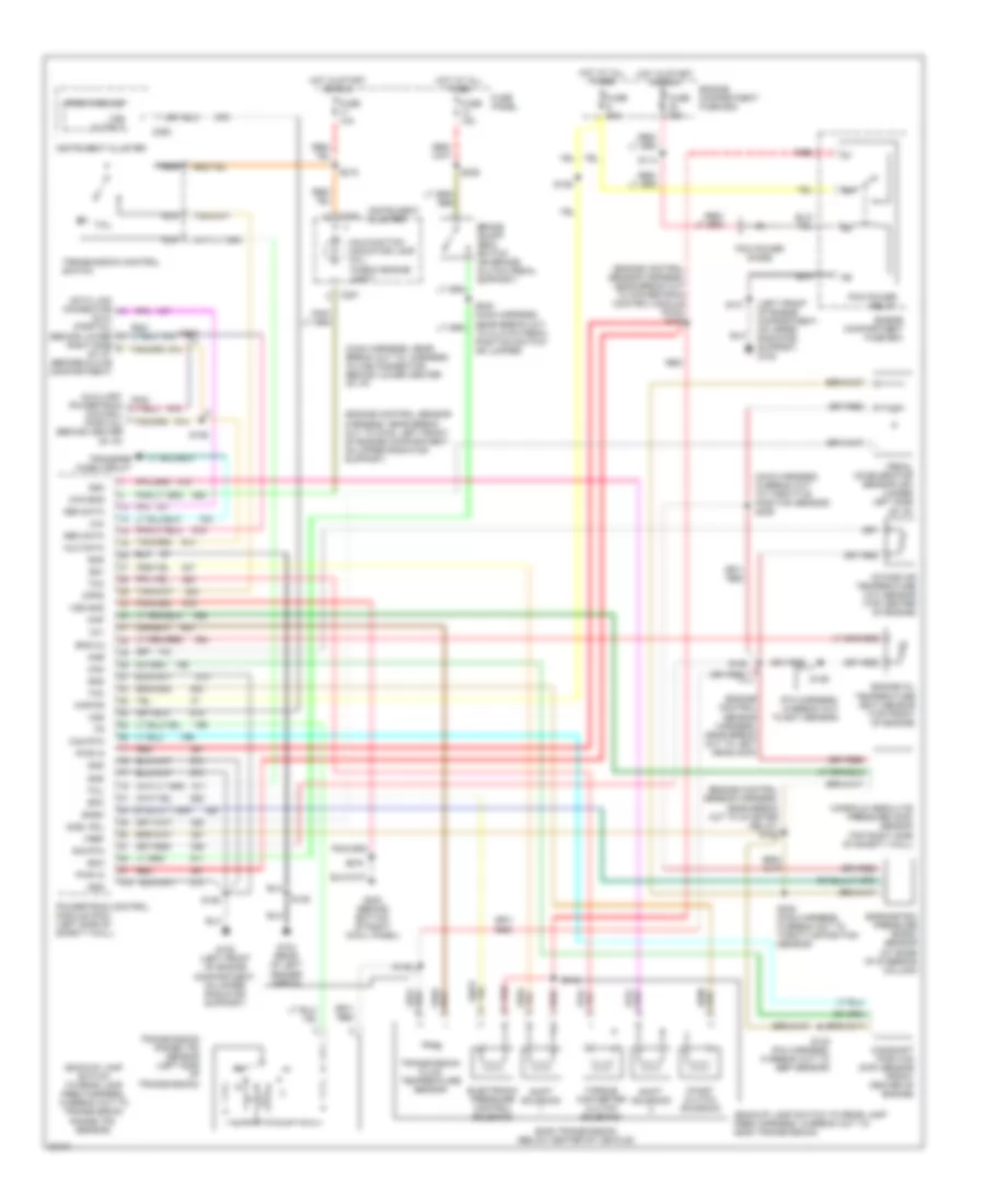
5.8L, Transmission Wiring Diagram for Ford Cab & Chassis F350 1996

List of elements for 5.8L, Transmission Wiring Diagram for Ford Cab & Chassis F350 1996:
- (backup lamp switch to rear lamp feed harness, in break out to transmission range (tr) sensor)
- (behind bottom of right cowl panel) g203
- (engine control sensor harness, near break out to brake warning resistor/diode assembly)
- (engine control sensor harness, near break out to brake warning resistor/diode assembly) s136
- (fuel charge harness, near break out to canister purge solenoid) (5.8l engine) (no location available) (7.5l engine)
- (fuel charge harness, near break out to fuel injector 4) (5.8l engine) (no location available) (7.5l engine)
- (left front of engine compartment, on upper radiator support) g108
- (transmission harness, near break out to e40d transmission)
- 4x4
- Boo
- Brake on/off (boo) switch (on brake/ clutch pedal support)
- C251
- C252
- Ccs
- Coast clutch solenoid
- Cse gnd
- Data
- E40d transmission (below center of vehicle)
- Ect
- Electronic pressure control solenoid
- Engine compartment fuse box
- Engine control sensor harness, near break out to powertrain control module (pcm))
- Engine coolant temperature (ect) sensor (center front of engine on, thermostat housing) (5.8l engine) (left front of engine, near left side of distributor) (7.5l engine)
- Epc
- Fuse 10a
- Fuse 15a
- Fuse 20a
- Fuse 30a
- Fuse panel
- G101 (right front of engine compartment, front of fender apron)
- G104 (rear of left fender apron)
- Gnd
- Hot at all times
- Hot in start or run
- Iat
- Ign
- Instrument cluster
- Intake air temperature (iat) sensor (top center front of engine near intake runner 6) (5.8l engine) (top center of engine, behind distributor) (7.5l engine)
- Kapwr
- Main harness, near break out to speed control amplifier
- Malfunction indicator lamp (mil)
- Manifold absolute pressure (map) sensor (no location available) (5.8l engine) (top right side of safety wall) (7.5l engine)
- Map
- Mil
- N d
- Nca
- Pcm power diode
- Pcm power relay
- Powertrain control module (pcm) (left side of safety wall)
- Psom module
- Red
- S102
- S106
- S135
- S137
- S146
- S148
- S161
- S163
- S169
- S215
- S216
- S236
- S240 (main harness, near break out to clutch pedal position switch or jumper)
- S246
- Shift solenoid
- Sig rtn
- Speed control servo/amplifier assembly (left side of engine compartment, near brake master cylinder)
- Ss1
- Ss2
- Tcc
- Tcil
- Tcs
- Tft
- Throttle position sensor (tps) (top right front of engine, on throttle body) (5.8l engine) (top left side of engine, on side of throttle body) (7.5l engine)
- Torque converter clutch solenoid
- Transfer case circuit
- Transmission control switch
- Transmission fluid temperature sensor
- Transmission range (tr) sensor (left side of transmission)
- Vip data link connector (left rear of engine compt, on bracket)
- Vip data link connector (partial) (left rear of engine compt, on bracket)
- Vref
- Vss gnd
- Vss input
- Vss output
7.3L
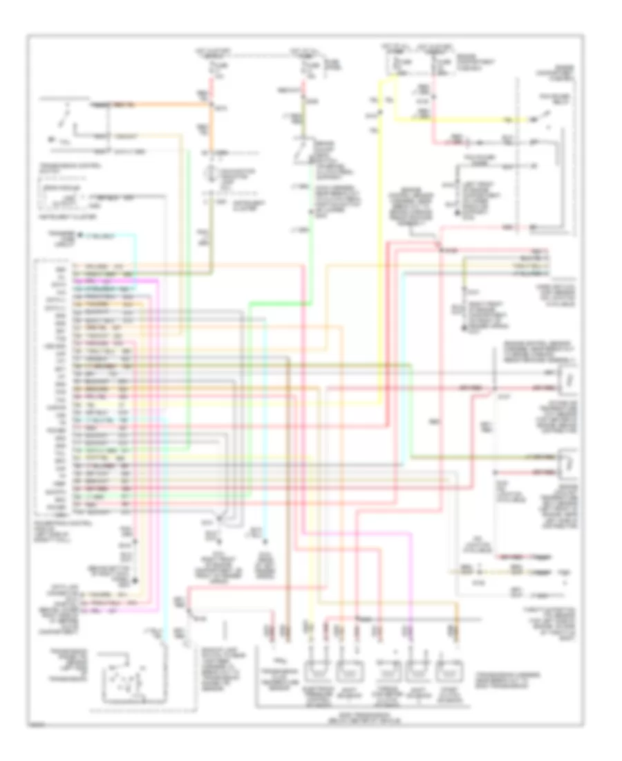
7.3L DI Turbo Diesel, Transmission Wiring Diagram for Ford Cab & Chassis F350 1996
List of elements for 7.3L DI Turbo Diesel, Transmission Wiring Diagram for Ford Cab & Chassis F350 1996:
- (backup lamp switch to rear lamp feed harness, in break out to e40d transmission)
- (backup lamp switch to rear lamp feed harness, in break out to transmission range (tr) sensor)
- (engine control sensor harness, near break out to g108, left front of engine compartment on upper radiator support)
- (engine control sensor harness, near break out to left headlamp)
- (engine control sensor harness, near break out to powertrain control module (pcm)) s157
- (engine control sensor harness, near break out to starter relay) s163
- (left front of engine compartment, on upper radiator support) g108
- (main harness, in break out to throttle position sensor) s239
- (main harness, near break out to, harness in-line connector, behind lower center of i/p)
- (pia harness, in break out to ect sensor)
- 4x4
- Acel pdl
- Amb
- Aux data
- Baro
- Barometric pressure (baro) sensor (at base of steering column)
- Boo
- Brake on/off (boo) switch (on brake/ clutch pedal support)
- C250
- C251
- C252
- Cam
- Cam rtn
- Camshaft position (cmp) sensor (front center of engine)
- Chk eng
- Coast clutch solenoid
- Cpps
- Data link connector (dlc) (partial) (behind lower
- E40d transmission (below center of vehicle)
- Electronic pressure control solenoid
- Eng oil
- Engine compartment fuse box
- Engine oil temperature (eot) sensor (top front of engine)
- Epc
- Fuse 10a
- Fuse 15a
- Fuse 20a
- Fuse 30a
- Fuse panel
- G104 (rear of left fender apron)
- G108 (left front of engine compartment, on upper radiator support)
- G203 (behind bottom of right cowl panel)
- Gen data
- Gnd
- Hot at all times
- Hot in start or run
- Instrument cluster
- Intake air temperature (iat) sensor (top center of engine)
- Kapwr
- Malfunction indicator lamp (mil) "check engine light"
- Manifold absolute pressure (map) sensor (top right side of safety wall)
- Map
- N d
- Nca
- Pcm power diode
- Pcm power relay
- Pedal accelerator sensor (ap) (under left side of i/p)
- Powertrain control (partial) (behind center of i/p)
- Powertrain control module (pcm) (left side of safety wall)
- Psom module
- Pwr in
- Red
- Right side of i/p, before glove compartment)
- S101
- S106
- S114
- S125
- S126
- S129
- S132 (pia harness, in break out to ebp sensor)
- S143
- S146
- S164
- S215
- S216
- S235 (main harness, in break out to throttle position sensor)
- S236
- S240 (main harness, near break out to clutch pedal position switch or jumper)
- S243
- Shift solenoid
- Sig rtn
- Ss1
- Ss2
- Tcc
- Tcil
- Tft
- Torque converter clutch solenoid
- Transfer case circuit
- Transmission control switch
- Transmission fluid temperature sensor
- Transmission range (tr) sensor (left side of transmission)
- Vref
- Vss
- Vss gnd
- Vss output
7.5L
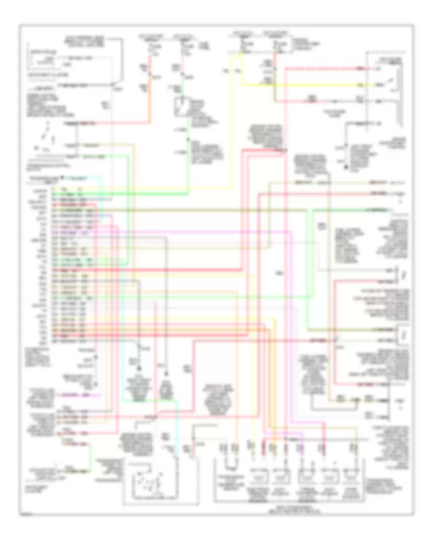
7.5L, Transmission Wiring Diagram, California for Ford Cab & Chassis F350 1996
List of elements for 7.5L, Transmission Wiring Diagram, California for Ford Cab & Chassis F350 1996:
- (behind bottom of right cowl panel) g203
- (engine control sensor harness, near break out to brake warning resistor/diode assembly)
- (left front of engine compartment, on upper radiator support) g108
- (no location available)
- (right front of engine, compartment, on front of fender apron) g101
- (transmission harness, near break out to e40d transmission)
- 4x4
- Backup lamp switch to rear lamp feed harness, in break out to transmission range (tr) sensor)
- Boo
- Brake on/off (boo) switch (on brake/ clutch pedal support)
- C250
- C251
- C252
- Ccs
- Coast clutch solenoid
- Data
- Data (+)
- Data (-)
- Data link connector (dlc) (partial) (behind lower right side of i/p, before glove compartment)
- E40d transmission (below center of vehicle)
- Ect
- Electronic pressure control solenoid
- Engine compartment fuse box
- Engine coolant temperature (ect) sensor (left front of engine, near left side of distributor)
- Epc
- Fuse 10a
- Fuse 15a
- Fuse 20a
- Fuse 30a
- Fuse panel
- G101 (right front of engine compartment, on front of fender apron)
- G104 (rear of left fender apron)
- Gnd
- Hot at all times
- Hot in start or run
- Iat
- Instrument cluster
- Intake air temperature (iat) sensor (top center of engine, behind distributor)
- Kapwr
- Maf
- Malfunction indicator lamp (mil)
- Mass air flow (maf) sensor (no location available)
- Mil
- N d
- Nca
- Pcm power diode
- Pcm power relay
- Power
- Powertrain control module (left side of safety wall)
- Psom module
- Red
- S101
- S102
- S104
- S135
- S136
- S137
- S146
- S148
- S161 (no location available)
- S169
- S215
- S216
- S236
- Shift solenoid
- Sig rtn
- Ss1
- Ss2
- Tcc
- Tcil
- Tcs
- Tft
- Throttle position (tp) sensor (top left side of engine, on side of throttle body)
- Torque converter clutch solenoid
- Transfer case circuit
- Transmission control switch
- Transmission fluid temperature sensor
- Transmission range (tr) sensor (left side of transmission)
- Vref
- Vss
- Vss gnd
- Vss output
7.5L, Transmission Wiring Diagram, Federal for Ford Cab & Chassis F350 1996
List of elements for 7.5L, Transmission Wiring Diagram, Federal for Ford Cab & Chassis F350 1996:
- (backup lamp switch to rear lamp feed harness, in break out to transmission range (tr) sensor)
- (behind bottom of right cowl panel) g203
- (engine control sensor harness, near break out to brake warning resistor/diode assembly)
- (engine control sensor harness, near break out to brake warning resistor/diode assembly) s136
- (fuel charge harness, near break out to canister purge solenoid) (5.8l engine) (no location available) (7.5l engine)
- (fuel charge harness, near break out to fuel injector 4) (5.8l engine) (no location available) (7.5l engine)
- (left front of engine compartment, on upper radiator support) g108
- (transmission harness, near break out to e40d transmission)
- 4x4
- Boo
- Brake on/off (boo) switch (on brake/ clutch pedal support)
- C251
- C252
- Ccs
- Coast clutch solenoid
- Cse gnd
- Data
- E40d transmission (below center of vehicle)
- Ect
- Electronic pressure control solenoid
- Engine compartment fuse box
- Engine control sensor harness, near break out to powertrain control module (pcm))
- Engine coolant temperature (ect) sensor (center front of engine on thermostat housing) (5.8l engine) (left front of engine, near left side of distributor) (7.5l engine)
- Epc
- Fuse 10a
- Fuse 15a
- Fuse 20a
- Fuse 30a
- Fuse panel
- G101 (right front of engine compartment, front of fender apron)
- G104 (rear of left fender apron)
- Gnd
- Hot at all times
- Hot in start or run
- Iat
- Ign
- Instrument cluster
- Intake air temperature (iat) sensor (top center front of engine near intake runner 6) (5.8l engine) (top center of engine, behind distributor) (7.5l engine)
- Kapwr
- Main harness, near break out to speed control amplifier
- Malfunction indicator lamp (mil)
- Manifold absolute pressure (map) sensor (no location available) (5.8l engine) (top right side of safety wall) (7.5l engine)
- Map
- Mil
- N d
- Nca
- Pcm power diode
- Pcm power relay
- Powertrain control module (pcm) (left side of safety wall)
- Psom module
- Red
- S102
- S106
- S135
- S137
- S146
- S148
- S161
- S163
- S169
- S215
- S216
- S236
- S240 (main harness, near break out to clutch pedal position switch or jumper)
- S246
- Shift solenoid
- Sig rtn
- Speed control servo/amplifier assembly (left side of engine compartment, near brake master cylinder)
- Ss1
- Ss2
- Tcc
- Tcil
- Tcs
- Tft
- Throttle position sensor (tps) (top right front of engine, on throttle body) (5.8l engine) (top left side of engine, on side of throttle body) (7.5l engine)
- Torque converter clutch solenoid
- Transfer case circuit
- Transmission control switch
- Transmission fluid temperature sensor
- Transmission range (tr) sensor (left side of transmission)
- Vip data link connector (left rear of engine compt, on bracket)
- Vip data link connector (partial) (left rear of engine compt, on bracket)
- Vref
- Vss gnd
- Vss input
- Vss output